Installation Installation
- 16 - - 17 -
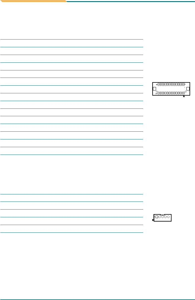
Connector: LVDS1
Type: One onboard DF13-30DS Header
Pin Description
1 VDD
3 LVDS CLK+
5 LVDS CLK-
7 GND
9 LVDS TX0+
11 LVDS TX0-
13 GND
15 LVDS TX1+
17 LVDS TX1-
19 GND
21 LVDS TX2+
23 LVDS TX2-
25 GND
27 LVDS TX3+
29 LVDS TX3-
Pin Description
2 NC
4 NC
6 NC
8 NC
10 NC
12 NC
14 NC
16 NC
18 NC
20 NC
22 NC
24 NC
26 NC
28 NC
30 NC
LVDS Panel Inverter Connector: INV1
Type: One onboard 1x5pin Wafer Header
Pin Description
1 +12V
2 GND
3 Backlight on/off
4 Brightness control
5 GND
LVDS1
INV1
2.3 Peripheral Ports
Pin Description
1 #STB
3 PD0
5 PD1
7 PD2
9 PD3
11 PD4
13 PD5
15 PD6
17 PD7
19 #ACK
Pin Description
2 #AFD
4 #ERR
6 #INIT
8 #SLIN
10 GND
12 GND
14 NC
16 BUSY
18 PE
20 SLCT
2.3.1 Parallel Port (Share with FDD)
Connector: LPT1
Type: One onboard 2x10Pin Header
2.3.2 USB Ports
Connector: USB1
Type: Onboard two USB ports
Connector: USB2
Type: One onboard 2x5pin Header
Pin Description
1 +5V
3 USBD1+
5 +5V
7 USBD0+
Pin Description
1 +5V
3 USBD2-
5 USBD2+
7 GND
9 GND
Pin Description
2 USBD1-
4 GND
6 USBD0-
8 GND
Pin Description
2 +5V
4 USBD3-
6 USBD3+
8 GND
10 NC
LPT1
USB2


