


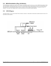
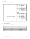

3.9.2 SEG-M Connectors
The chart below describes the connectors on the SEG-M.
Connector Description Pin Configuration
J1 RS-485 Data Connector
Pin Label Description
1 A RS-485 Data A (+)
2 B RS-485 Data B (-)
3 GND RS-485 Data GND
4 A RS-485 Data A (+)
5 B RS-485 Data B (-)
6 GND RS-485 Data GND
S1 Power/RS-232 Data Connector
Power/RS-232 Connector (used to plug onto
backplane)
TS1
RS-232 Data, RS-485 Data and Power
Terminal Strip
Pin Label Description
1 V+ Power Supply Positive
2 GND
Power Supply Negative/
Data Ground
3 EGND Earth Ground
4 A1 RS-232 Receive Data
5 A0 RS-232 Transmit Data
6 A RS-485 Data A
7 B RS-485 Data B
3.9.3 SEG-M LED Indicators
The chart below describes the LED indicators on the SEG-M.
LED Designator Label Description
LED1 Power SEG-M Power
LED7 TX RS-485 Transmit
LED5 RX RS-485 Receive
LED6 TX RS-232 Transmit
LED4 RX RS-232 Receive
Document Number: 6066005, Rev 3.2 Page 13 of 34