


Page 18
5.0 Controls and indicators
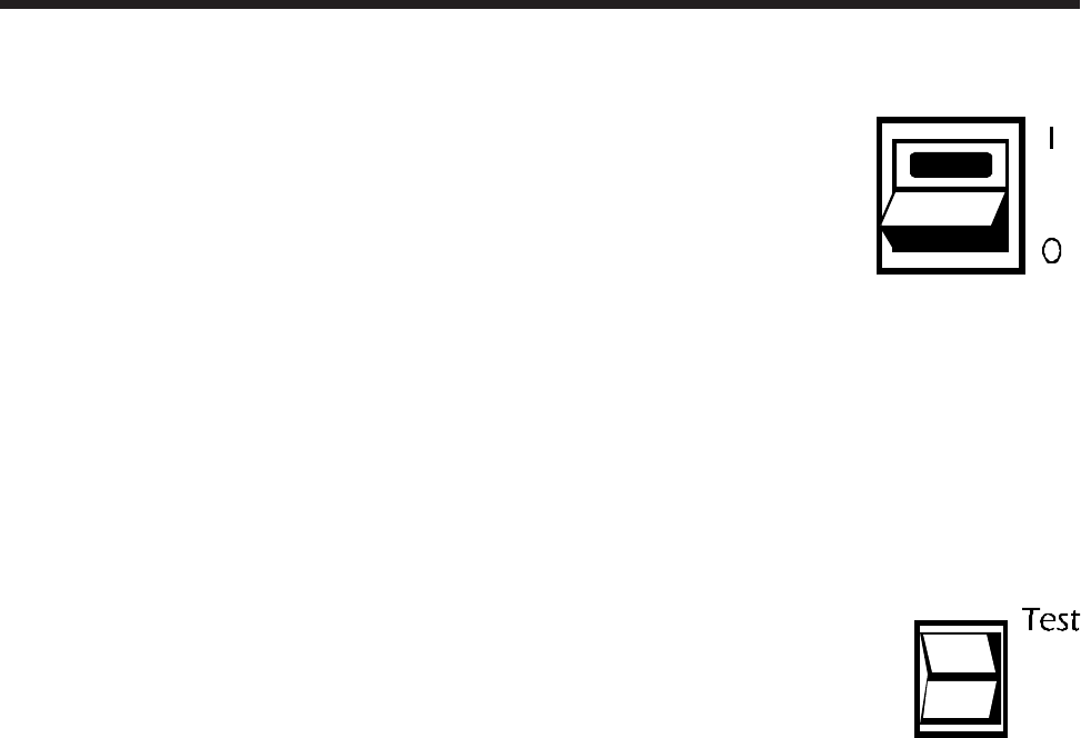
5.1 Power I/0 switch
The power I/0 switch controls power to the UPS and its output
receptacles. When the switch is on, the UPS operates and your
computer equipment will be powered. When the switch is off,
the UPS is de-energized and your equipment is unpowered. If
your equipment switches are left on, the entire system can be
operated by using just the power I/0 switch.
Under normal conditions, the lamp within the power I/0 switch illuminates
whenever the UPS is switched on. When the UPS is operating on-battery, the
lamp flashes. The lamp will flash, and the UPS will shut down, in the event of an
internal UPS fault.
5.2 Test switch (on units so equipped)
When the Test switch is pressed, the UPS simulates a power outage
and transfers your load to the alternate power source. This feature
allows you to determine that computer equipment protected by
the UPS operates normally during transfers. It also provides a
convenient means of testing the UPS’s battery. If the Test control
is held depressed, the UPS will operate your equipment from power derived
from the battery continuously. If during the test the low battery warning is
sounded prematurely and the load is known to be normal, then the battery is
weak and requires extended recharge or replacement (see section 7.0).
5.3 Audible alarm
During a utility failure, the UPS emits a series of four beeps once every 30 seconds
to warn you that your equipment is operating from a source of power which is
limited in duration. In the event of an extended utility failure, the UPS will sound
continuous beeps 2 minutes in advance of shut down due to battery capacity
exhaustion. Once shut down, the UPS will cease sounding the alarm. In the event
the UPS encounters a severe overload, the UPS will shut down and emit a loud
tone. The alarm is reset when the UPS is turned off. The UPS will shut down and
sound the audible alarm when an internal fault is detected.