9
4
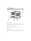
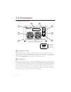
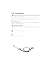
EU separating screw
The Electronics Unit separating screw is turned counterclockwise to remove the EU
for service. If this action is taken while the UPS is on-line, the UPS will automatically
transfer to bypass operation. See the Difficulty section of this manual for the proper
EU replacement procedure.
Note: The UPSs display is blank when the EU separating screw is loosened. Control
of the UPS is regained when the screw is tightened and any control button is
pressed.
5
Wiring inspection cover
When removed, the wiring inspection cover reveals the output wiring connections to
the UPS. It is necessary to inspect the connections during installation as the wires may
move when the power distribution plate is reattached. See the Installation section of
this manual.
6
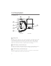
Power distribution plate
The standard furnished power distribution plate is removable for access to the input
and output wiring terminations, and to the input voltage selection taps. Optional
power distribution plates with wiring devices other than those provided as standard
can be ordered from the factory and installed in the field.
6a
IEC 320 C13 receptacles
A total of eight IEC 320 C13 outlets are provided for multiple small loads.
6b
IEC 320 C13 receptacle circuit breaker
Each row of quad IEC 320 C13 output receptacles is protected by a 12 Amp circuit
breaker. This protection is necessary because the UPS is capable of delivering more
than the receptacle's maximum current rating.
7
Electrical fittings knockouts
Knockouts appropriate for use with 0.75-in. (19mm) and 1-in. (25mm) electrical
cable clamp fittings are provided at the input cable plate, and at the output power
distribution plate.
8
Input cable plate
The input cable plate is removed during the input wiring installation.
3.0 Presentation


