


4
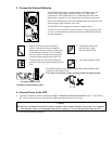
5. Install PowerChute and Accessories
For additional computer system security, install PowerChute UPS monitoring software. It provides automatic unattended
shutdown capabilities on most major network operating systems. Once PowerChute is loaded, install the PowerChute
®
black communication cable between UPS and computer. See the Software Installation: Instruction Sheet for details.
Notes:
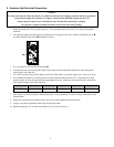
This UPS is equipped with one accessory slot. See the APC website (www.apc.com) for available accessories. If a
standard accessory is installed in this UPS, follow the installation instructions for the accessory, which are
included in the package.
6. Program the SU5000UXI with the number of external battery packs connected
Smart-UPS UXI models are not designed to know how many external battery packs are connected to them. A customer
must program the Smart-UPS UXI with the appropriate number of external batteries in one of four ways.
It is important to follow these instructions. The number of batteries affects the runtime calculations which Smart-UPS
performs when it is running on battery power.
Use PowerChute®
®®
® plus version 5.x for Windows 95, Windows 98, Windows NT.
PowerChute® plus 5.x for Windows NT is compatible with NT 3.5.1 SP5, NT 4.0 Workstation (at least SP1), or NT
4.0 Server (at least SP1).
Install the software per the instructions on the CD.
After rebooting the computer, access the PowerChute® plus graphical user interface.
1. Click on Configuration.
2. Click on UPS Operating Parameters.
3. Adjust the External Battery Pack field to the appropriate number of external batteries.
4. Click OK.
Use the Terminal Program to change the number of external battery packs
Terminal is used in Windows 3.1x, Windows for Workgroups, and Windows NT 3.51.
1. EXIT out of the PowerChute® plus Server. In the case of Windows NT, the UPS Service must be stopped.
2. Go to: Program Manager > Accessories > Terminal. Double-click on the Terminal icon.
3. Select the COM port to which the black-colored interface cable is attached as the Connector.
4. The COM port settings are 2400 baud, 8 data bits, 1 stop bit, no parity, flow control is Xon/Xoff.
5. Click OK.
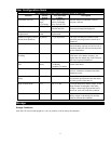
6. Continue with the steps in Table 1, page 5.