


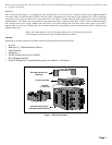
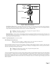
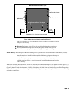
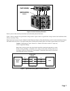
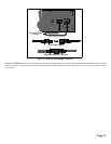
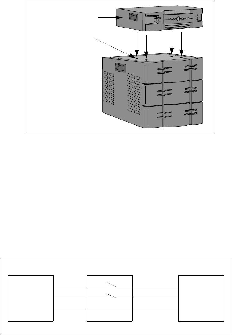
Figure 6. Inverter Assembly Placement
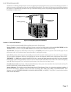
Remove power at the electricity board meter (circuit breaker panel) of the home.
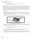
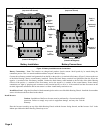
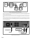
Figure 7 shows a diagram of a typical home wiring scenario. Figure 8 shows a typical home wiring scenario after installation of the
Inverter Assembly wiring.
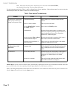
Note: The Power Inverter can serve inductive loads (flourescent lamps, ceiling and table fans), resistive loads (incandescent lamps),
and SMPS loads (television). The typical backup time with the primary battery pack at full load is approximately two (2) hours.
Caution: Connecting the Power Inverter to a branch circuit that exceeds 16 amps may
result in equipment damage.
Note: Home wiring to power the desired loads should be routed and connected to a single
branch circuit providing a maximum of 16 amps to the circuit, Wiring must be in
accordance with local electric codes and standards. Connected loads must not exceed 500
watts when the Inverter is On Battery.
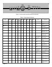
Figure 7. Typical Home Wiring Before Inverter Installation
Page 7
Inverter Assembly
(“feet” not shown)
Indents (4 places)
(Wire Harness not
Shown)
L
N
E
L
N
E
Electricity
Board
Meter
Double-Pole
Switch
Load
Existing Wiring