


User Manual 990-9178A
DC MX06 40A Shelf Page 14 of 44 18
th
FEB 02
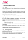
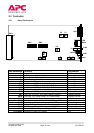
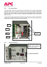
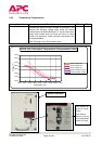
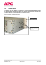
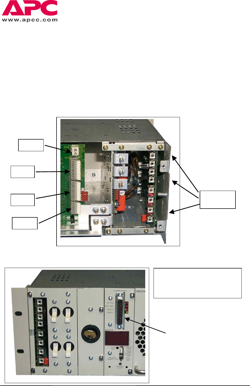
2.4.2 Rear Access Alarms
To access the alarm outputs first ensure batteries are disconnected from the system by setting battery
connection switch to “OFF” via controller front panel (see section 2.3) and by turning the external battery
breaker off. The input mains supply must then be turned off by operating the local isolator or disconnection
device. Remove the rear cover to leave the view as shown below. Labelled are the 3 signal output
connectors SK14, SK17 and SK18 and also the temperature compensation connector SK19, where a
thermistor is wired.
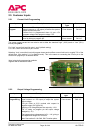
To use a particular alarm signal simply strip the ends of your alarm cables and enter into connectors by
pushing down on respective lever, push in alarm cable and release lever to clamp cable. Cables should be
routed through one of the knockout panels in the side of the shelf.
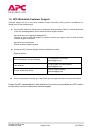
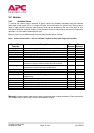
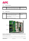
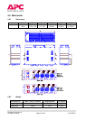
2.4.3 Front Access Alarms
SK19
SK17
SK14
SK18
Knockout
panels
Alarms socket SK4
The front access alarms are
available from a 25 way ‘D’
connector socket (SK4) mounted
in the controller front panel.
1
2
3
4
DISTRIBUTION
1
2
3
4