


User Manual 990-9178A
DC MX06 40A Shelf Page 29 of 44 18
th
FEB 02
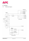
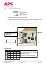
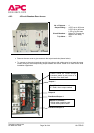
4.1.3.2 Front access connection
To connect the input supply to the MX06 40A Shelf proceed as follows:
• The AC input current to the system should also be limited by an appropriate device in the
event of a short circuit as defined in EN60950 to protect the internal wiring of the end use
equipment. The device(s) should be rated accordingly.
• Ensure that the AC supply intended for connection is isolated, locked off and under single
operator control.
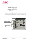
• The main circuit board should have been configured for 3-phase star use by removal of LK2
and LK3. This is normally factory configured.
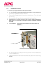
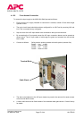
• Strip the ends of the AC Input cables to be connected to the Input terminal block.
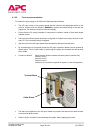
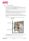
• By unscrewing the 2 front panel screws the AC Input connection drawer can be opened as
shown below. The AC Input cable is fed through the gland and screwed into the terminal
block visible.
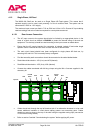
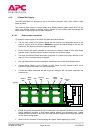
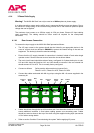
• Connect as follows: Safety earth to position marked with earth symbol (connect first)
Phase 1 to AC1
Phase 2 to AC3
Phase 3 to AC4
Neutral to AC2 (neutral is required as system is a star configuration)
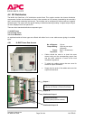
• The alarm card adjacent to the AC Input drawer may need to be removed for easier access
to the terminal block screws.
• Refer to section 5 entitled “Commissioning the system” before applying AC power.
Cable Gland
Terminal Block