


User Manual 990-9178A
DC MX06 40A Shelf Page 17 of 44 18
th
FEB 02
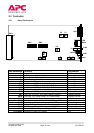
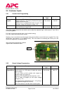
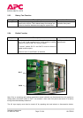
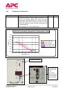
2.5.3 Battery Test Function
Input Description Location
Battery Test
Front panel momentary push button. Push and hold drops
output volts to 45Vdc. This is below battery float voltage and
is used to check the batteries can supply the system load.
Push button mounted on
controller front panel.
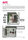
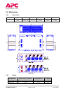
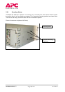
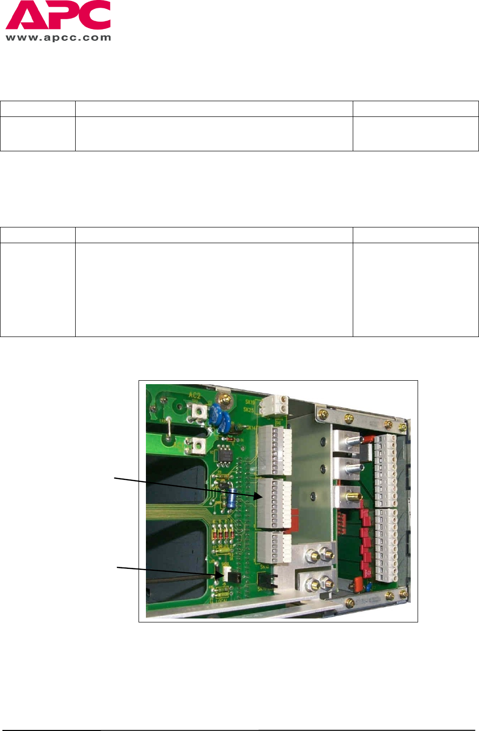
2.5.4 Enable Function
Note: Prior to accessing and making connections ensure batteries are disconnected from the system by
setting battery connection switch to “OFF” via controller / alarm card front panel (see section 2.3) and by
turning the external battery breaker off.
The AC input supply must then be turned off by operating the local isolator or disconnection device.
Input Description Location
Enable
Back-plane circuit board mounted 3-way Molex header. Link
pins 1 and 2 with supplied link for “local” enable of rectifier
outputs. Link pins 2 and 3 for “remote” enable.
If “remote” enable SK17-1 and SK17-6 must be linked to
enable rectifier outputs.
System is set to “Local Enable” as standard
SK22 (mounted on back-
plane board).
SK22
SK17