


Section 3. Installation
Home UPS Placement
Note: Once the unit has been completely installed, it is not desirable to move it.
Location selection - Ensure the area where the unit is to be placed is not in direct sunlight (surfaces may become hot).
Further ensure the unit is placed in a dry area away from sources of liquids, and that the vents on each side have at least 15 cm
(6 inches) of unobstructed clearance.
Battery Connection
Connect the red battery terminal lead (protrudes from the lid) to the positive (+) terminal of the battery and connect the black
battery terminal lead (protrudes from the lid) to the negative (-) terminal.
Install Home UPS
Caution: Installation of the Home UPS must be performed by a licensed and qualified
electrician. Failure to comply may result in equipment damage, and may also void the
Warranty.
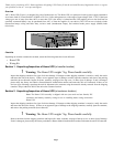
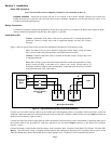
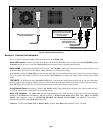
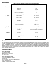
Figure 2 shows a typical home wiring scenario after installation of the Home UPS Assembly wiring.
Note: The Home UPS can serve inductive loads (fluorescent lamps, ceiling and table
fans), resistive loads (incandescent lamps), and SMPS loads (television).
Caution: Connecting the Home UPS to a branch circuit that exceeds 16 amps may result
in equipment damage.
Note: Home wiring to power the desired loads should be routed and connected to a single
branch circuit providing a maximum of 16 amps to the circuit, Wiring must be in
accordance with local electric codes and standards. Connected loads must not exceed 360
watts when the Home UPS is On Battery.
Figure 2. Typical Home Wiring After Home UPS Installation
Connect one end of the electrical cable from the double-pole switch lighting circuit in accordance with local electric codes and
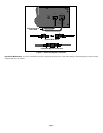
standards. Connect the other end of the electrical cable to the provided IEC connector, and then to the rear panel Input connector on
the Home UPS Assembly (Figures 2 and 3).
Connect one end of the electrical cable from the load in accordance with local electric codes and standards. Connect the other end of
the electrical cable to the provided IEC connector, and then to the rear panel Output connector on the Home UPS Assembly
(Figures 2 and 3).
Connect the battery wiring harness from the battery to the rear panel input connector of the Home UPS (Figure 3) marked 12V
Battery. Once the home wiring is complete and the batteries are connected to the Home UPS Assembly, turn on power at the
Electricity Board Meter then at the Double-Pole Switch Lighting Circuit. The Home UPS will automatically turn on.
Page 2
E
N
L
E
N
L
Electricity
Board
Meter
Double-Pole
Switch Lighting
Circuit
Load
Input
Output
Wiring for Home UPS