


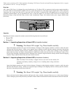
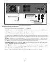
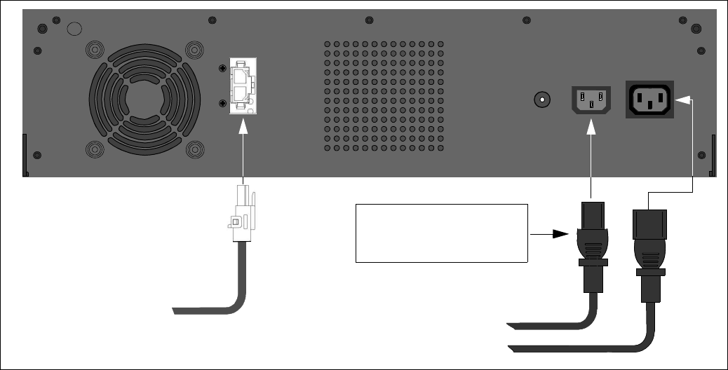
Figure 3. Home UPS Connections
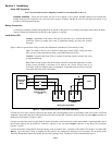
Section 4. Controls and Indicators
Please review this section thoroughly before applying power to the Home UPS.
Home UPS Controls - Controls provided on the Home UPS consist of the holiday mode switch marked AWAY/HOME, and the
Test/Mute switch, as well as a rear panel Push to Reset circuit breaker, and are defined in the following:
AWAY/HOME - (also known as the holiday mode switch) - In the HOME position, this two-position rocker switch (Figure 4) sets
the Home UPS so that it will switch to battery output when there is a utility power outage.
In the AWAY position, the Home UPS goes into standby mode and will not switch to battery power in the event of a power outage.
This is to conserve the batteries. However, in this position, the Home UPS will charge the batteries until a utility power failure
occurs.
TEST/MUTE - In TEST mode, when ON MAINS LED is lit, on pressing this push button, the unit will do self test to determine
the state of the system. During On Battery self test it will also show the load status which can be used to find out the load capacity.
In the MUTE position (push in for 5 seconds), this push button switch silences the low battery buzzer.
Circuit Breaker Switch (Rear Panel) - When in ON MAINS mode, if the system draws more than 10A, circuit breaker will trip.
To reset the circuit breaker switch, push the switch fully inward.
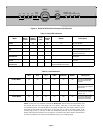
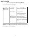
Home UPS Indicators - The Home UPS provides light emitting diode (LED) indicators (Figure 4) to show the operational
condition of the Home UPS and batteries. Indicators consist of Inverter Load Status (25%, 50%, 75%, 100%, and OVER
LOAD). Other indicators consist of: INVERTER DISABLE, ON MAINS, ON BATTERY, and FAULT). Using Table 1,
determine the condition of the Home UPS and battery.
Cold Boot - To turn on the Home UPS on Battery Mode, press the Test-Mute button and hold it for 2-3 seconds.
Page 3
INPUT OUTPUT
Push to Reset
N
L
L N
Output : 230V, 5A, 50HZ
Input : 230V, 5A, 50Hz
12V Battery
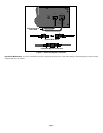
Battery Wiring Output Harness
(Red and Black Wires)
From Electricity Board Meter
To Load
(through Double-Pole
Switch Lighting Circuit)
These connectors are provided
with the Home UPS Assembly
and must be installed
on to the wiring.
+Ve
-Ve