


6
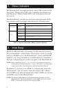
5. Status Indicators
The MasterSwitch
™
has eight receptacle status LEDs located on the
front panel. When a status LED is on, it indicates the related recep-
tacle has power; When a status LED is off, its receptacle does not
have power.
The MasterSwitch
™
also has two network connection status LEDs,
also located on the front panel, that indicate the following states:
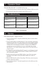
LED State Indication
Link-TX/RX
Blinking
Green
MasterSwitch™ is connected to a working
network.
Off
Network or MasterSwitch™ connection failure.
Status
Solid Green
MasterSwitch™ is ok.
Blinking
Green
Network configuration values have not been
defined for the MasterSwitch™.
Flashing
Red (Slow)
Processing bootp.
Solid Red
Hardware Failure.
Table 1: Network Connection (10Base-T) Status Indicators
6. Initial Setup
Before the MasterSwitch
™
can operate over the network it needs to
have certain address values defined. These values can be set (config-
ured) by a BOOTP server (the MasterSwitch
™
comes with BOOTP
enabled) or by using a terminal (or terminal emulator) connected to
the 9-pin configuration port on the front panel of the MasterSwitch
™
.
NOTE: Refer to the MasterSwitch
™
- User’s Guide for information on the initial
configuration of the MasterSwitch
™
. A copy of this guide, in portable data
format is provided on the diskette that came with the MasterSwitch
™
.
In addition, if you want to use SNMP to configure and control the
MasterSwitch
™
, you will need to load and compile APC’s Master-
Switch-MIB at any network management station (NMS) you will use
for SNMP control of the MasterSwitch
™
.
NOTE: The MasterSwitch-MIB is provided on the diskette that came with the
MasterSwitch
™
. See the documentation for the NMS you want to use this
MIB for instructions on loading and compiling MIBs.