


Certified Electrician’s Instructions
40kW InfraStruXure PDU 9
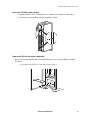
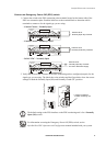
Connect an Emergency Power Off (EPO) switch
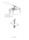
1. Connect the switch to the EPO connection point terminals located on the bottom side of the
PDU user connection plate. Read the label next to the terminal block to determine which
terminals to connect to for the signal type you are using:
– Contact Closure—Normally Open
– Contact Closure—Normally Closed
– 24VAC/VDC—Normally Open
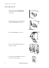
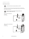
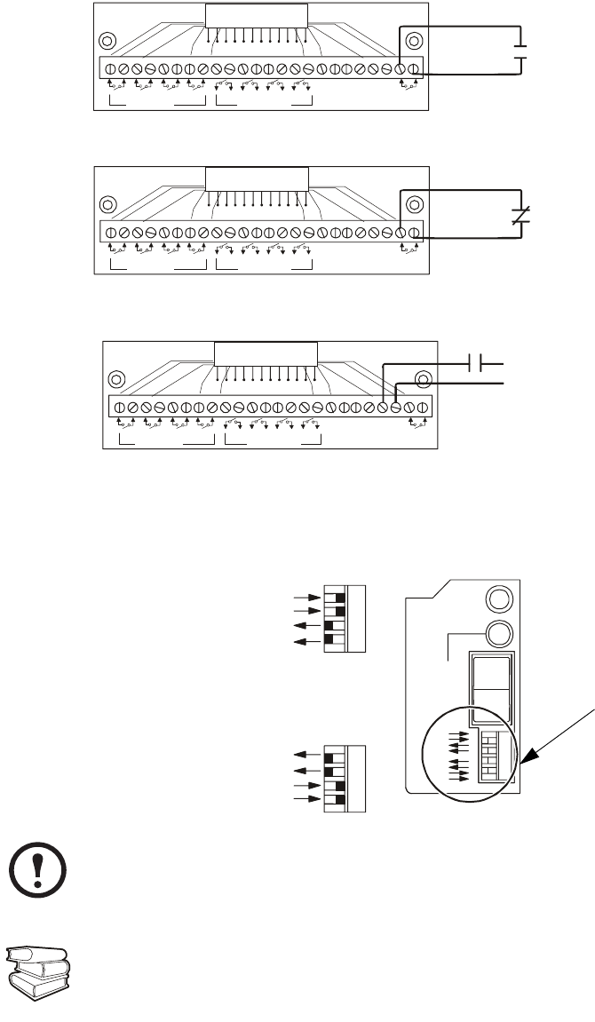
2. Verify that the EPO DIP switches on the PDU monitoring unit are configured properly for the
signal type you are using. The labels above the switches and the figure below show the correct
settings for both the Normally Open (NO) and Normally Closed (NC) position.
Note
The default setting on the EPO interface on the PDU monitoring unit is for a Normally
Open (NO) switch.
See als
o
For information on testing the Emergency Power Off (EPO) switch, see the
InfraStruXure PDU Operation and Configuration manual included with your system.
1 234
ATS EN
ATS 0
ATS 1
ATS 2
EPO
Contact
–
+
EPO 24V
AC/DC
Contact Inputs
Contact Outputs
USER INTERFACE
© 2001 APC
MADE IN USA
External set of
Normally Open Dry Contacts
1 234
ATS EN
ATS 0
ATS 1
ATS 2
EPO
Contact
–
+
EPO 24V
AC/DC
Contact Inputs
Contact Outputs
USER INTERFACE
© 2001 APC
MADE IN USA
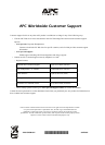
External set of
Normally Closed Dry Contacts
1 234
ATS EN
ATS 0
ATS 1
ATS 2
EPO
Contact
–
+
EPO 24V
AC/DC
Contact Inputs
Contact Outputs
USER INTERFACE
© 2001 APC
MADE IN USA
24V AC or DC Power Supply
External set of
Normally Open Dry Contacts
NO
NC
TRIPPED
ARMED
TEST
EPO
Normally ClosedNormally Open
or 24V AC/DC
Location of switches
on PDU monitoring unit