


22 Smart-UPS RT 15000/20000 VA 230 Vac Stack/Rack-Mount 6U User Manual
Emergency Power Off (EPO)
The output power can be disabled in an emergency by closing a switch connected to the EPO.
Adhere to national and local electrical codes when wiring.
The switch should be connected in a normally open switch contact. External voltage is not required; the switch
is driven by 12 V internal supply. In closed condition, 2 mA of current are drawn.
The EPO switch is internally powered by the UPS for use with non-powered switch circuit breakers.
The EPO circuit is considered a Class 2 circuit, (UL, CSA standards) and an SELV circuit (IEC standard).
Both Class 2 and SELV circuits must be isolated from all primary circuitry. Do not connect any circuit to the
EPO terminal block unless it can be confirmed that the circuit is Class 2 or SELV. If circuit standard cannot be
confirmed, use a contact closure switch.
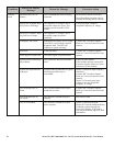
Use one of the following cable types to connect the UPS to the EPO switch.
• CL2: Class 2 cable for general use.
• CL2P: Plenum cable for use in ducts, plenums, and other spaces used for environmental air.
• CL2R: Riser cable for use in a vertical run in a floor-to-floor shaft.
• CLEX: Limited use cable for use in dwellings and for use in raceways.
• For installation in Canada: Use only CSA certified, type ELC, (extra-low voltage control cable).
• For installation in other countries: Use standard low-voltage cable in accordance with national and
local regulations.
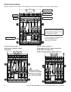
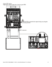
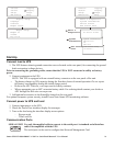
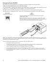
EPO PORT
(located on rear panel)
EPO
Connector
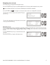
Strip the insulation from one end of each wire to be used for
connecting the EPO.
Insert a screwdriver into the slot above the terminal to be wired.
Insert the stripped wire into the terminal. Remove the screwdriver to
secure the wire in the terminal. Repeat for each terminal.