


Smart-UPS RT 15000/20000 VA 230 Vac Stack/Rack-Mount 6U User Manual 21
Start-Up
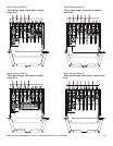
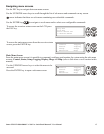
Connect load to UPS
1. The UPS features chassis ground connection screws located on the rear panel, for connecting the ground
leads on transient voltage devices.
Prior to connecting the grounding cable, ensure that the UPS is NOT connected to utility or battery
power.
2. Connect equipment to the UPS.
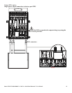
NOTE: This UPS is equipped with an external battery connector on the rear panel of the unit.
• The battery charges to 90% capacity during the first three hours of normal operation. Do not expect
full battery run capability during this initial charge period.
• Refer to the APC Web site, www.apc.com for battery runtimes.
• Where appropriate use an APC extension battery cable. For ordering details contact your dealer or
APC through the Web site www.apc.com.
3. Add optional accessories to the SmartSlot located on the rear panel.
For optimal computer system security, install PowerChute Smart-UPS monitoring software.
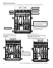
Connect power to UPS and load
1. Connect input power to the UPS.
2. Check the PowerView interface display for messages.
3. Turn on the load using the interface display menu options.
– Bypass mode
– Turn Load On
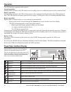
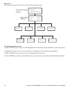
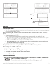
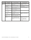
Communication Ports
Language
Contrast
Beeper Setup
Display Setup
Control
Status
Setup
Batteries
Logging
Display
Diags
Help
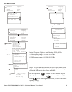
Beeper at
Volume
Key Click
Beeper Setup
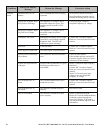
Raw Status Dump
M states =
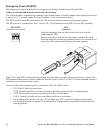
Control
Status
Setup
B
atteries
Logging
Display
Diags
Help
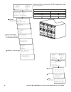
F
ault & Diagnostics
System Information
Switch Status
Raw Status Data
No Active alarms
System Information
FW-revision
SN
UPS Size
Fault &
Diagnostics
System
Information
Raw Status
Data
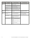
SERIAL PORT
Use only the supplied cable to connect to the serial port. A standard serial interface
cable is incompatible with the UPS.
The serial port can be used to configure that Network Management Card.