


Inspection
Inspect the UPS upon receipt. Notify the carrier and dealer if there is damage. The
packaging is recyclable; save it for reuse or dispose of it properly.
Placement
Install the UPS in a protected area that is free of excessive dust and has adequate
air flow. Do not operate the UPS where the temperature and humidity are outside
the specified limits.
Warning: Changes or modifications to this unit not expressly approved
by the party responsible for compliance could void the warranty.
Installation
To install this UPS, please follow the installation instructions in the
Smart-UPS Quick Reference Guide.
If this UPS is equipped with a SmartSlot for accessories, see the APC
Website (www.apc.co.jp) for available accessories.
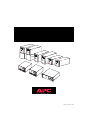
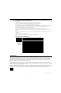
Rear Views Tower Units
Note: The SU2200J does not have the battery expansion slot.
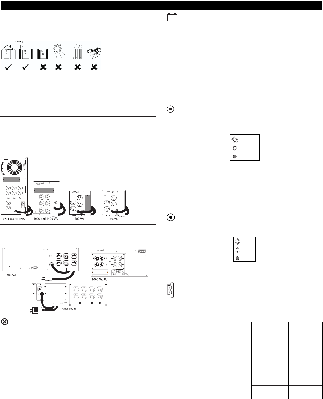
Rear Views Rack Mount Units
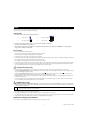
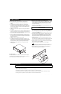
Connect Ground Leads to TVSS Connector (Optional)
The UPS features a TVSS connector for connecting the ground lead on transient
voltage surge-suppression (TVSS) devices such as telephone and network line
protectors. The TVSS connector provides grounding through the UPS’s power
cord ground conductor. To make a connection to the TVSS connector, loosen the
screw and connect the surge suppression device’s ground lead. Tighten the screw
to secure the lead.
Charge the battery
The UPS charges its battery whenever it is connected to utility power. For best
results, charge the battery for 2.5 hours before use. It is acceptable to use the UPS
without first charging the battery, but on-battery run time may be reduced until the
battery charges.
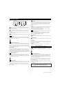
Voltage Sensitivity
The UPS detects line voltage distortions such as spikes, notches, dips, and swells,
as well as distortions caused by operation with inexpensive fuel-powered genera-
tors. By default, the UPS reacts to distortions by transferring to on-battery operation
to protect the loads. Where power quality is poor, the UPS may frequently transfer
to on-battery operation. If the loads can operate normally under such conditions,
battery capacity and service life may be conserved by reducing the sensitivity of
the UPS.
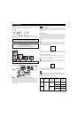
To reduce UPS sensitivity, press the Sensitivity button on the rear panel. Use
a pointed object such as a pen to press the button. Press it once to set the UPS’s
sensitivity to reduced. Press it again to set the sensitivity to low. Press the button a
third time to reset normal sensitivity.
When the UPS is set to normal sensitivity, the LED is brightly lit. When it is set to
reduced sensitivity, the LED is dimly lit. When it is set to low sensitivity, the LED
is off.
Low Battery Warning Interval
By default, the low battery warning occurs when there are approximately two min-
utes of on-battery run time remaining. This may not be enough time to gracefully
shut down some protected computer systems.
To change the warning interval, press the rear panel Sensitivity button while
pressing and holding the front-panel on/test button. Use a pointed object such as a
pen to press the configuration button.
Press the Sensitivity button once to set the low battery warning interval to approxi-
mately five minutes. Press it again to set the interval to approximately seven
minutes. Press the button a third time to reset the interval to two minutes.
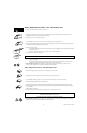
Battery Pack Connector (3000 VA tower and 3000RM5U models only)
Use the battery pack connector to connect the optional external battery pack.
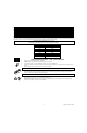
2200VA and 3000VA Input Power Connectors
Model Standard Maximum Available input Maximum
input power output power power power with
connector with standard connectors available
connector connector
2200 VA/
20 Amp 1500 VA /
1600 W
1500 W
2200 VA
30 Amp 2200 VA /
30 Amp
1600 W
2250 VA/
30 Amp 2250 VA /
3000 VA
2250 W
2250 W
Hard wired 3000 VA /
2250 W
2 990-7061A, Revision 2 12/98
Initial Startup
normal
reduced
low
2 min.
5 min.
7 min.