


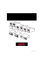


Installation Tips for Rack Mount Units
Please observe the following items when installing the Rack Mount UPS:
• The UPS comes with standard 19” (46.5 cm) rack mount brackets
installed.
• The 3000 VA model of the UPS is supplied with L channel supports.
These supports may be used with this model to ease installation for a 19”
rack. The L channel supports are available as an accessory for the 1400
VA model. Contact your dealer or the factory at the number listed under
Service for more information.
• Caution: The 3000 VA model requires two or more people to install due
to its weight.
• The UPS is not supplied with screws to attach the mounting bracket (ears)
to the rack, as the size of screw varies according to the type of rack used.
• UPSs are heavy. Select a rack location sturdy enough to handle the weight.
Try to mount the UPS near the bottom of the rack.
• Select a rack location with adequate air flow that is free from excessive
dust. Ensure that the air vents on the sides of the UPS are not blocked. Do
not operate the UPS where temperature or humidity are outside the limits
listed under Specifications.
• Caution: Remove the UPS before moving the rack.
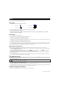
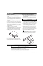
• Two additional sets of bracket holes, shown below at asterisks (*), are
located on the sides of the UPS. These holes allow mounting the brackets
with a three inch or six inch setback. Move the mounting brackets back if
desired to optimize the esthetic or physical requirements of the rack.
• Caution: Check the rack to make sure it won’t tip after moving the
mounting brackets.
Rack Mount Options
Accessory receptacle plates are available for the 3000 VAmodel. These plates
offer different receptacle configurations and hard wire installation. Contact your
dealer or the factory at the number listed below in Service.
Installing the L Channel Supports on Rack Mount Units
1. Verify the contents of the kit. It contains: two adjustable-length L-channel
supports included with the 3000 VAmodel only, four clip nuts, eight 10-
32 x 1/2” flat-head screws, and eight washers. The washers are for use
with square rack holes only.
2. If the rack’s rails have threaded holes, drill out the appropriate front rail
rack holes with a 7/32” drill bit.
Note: The mounting rails do not require clips. The threaded insert
is part of the actual rail.
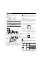
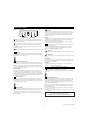
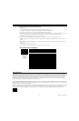
3. Secure the front of the support to the front cabinet rack using two 10-32 x
1/2” flat-head screws (shown in blow-up below). Note that the front ear of
the L-channel support has a square cutout on the mounting ear
➊, and the
rear ear has no cutout
➋. For cabinets with square rack holes, use a wash-
er under the head of each screw.
4. Loosen the two 10-32 x 5/16” pan-head screws that lock together the two
halves of the L-channel support
➌. Slide the outer half of the support to
the rear until it contacts the rear rack of the cabinet. If the rack uses
threaded holes, drill out the appropriate rear rail rack holes with a 7/32”
drill bit (see Step 2).
5. Secure the rear of the support to the rear cabinet rack using two 10-32 x
1/2” flat-head screws (see full picture below). For cabinets with square rack
holes, use a washer under the head of each screw (see blow-up below).
6. Securely tighten the two 10-32 x 5/16” pan-head screws that lock together
the halves of the L-channel support
➌.
7. Repeat steps 2 through 5 to install the other L-channel support.
8. Mounting clips are required for the mounting ears on the UPS. Use
the enclosed template (990-0195) to install the clips for the UPS ears.
9. Slide the UPS onto the L-channel supports and use rack hardware to
secure the UPS mounting ears to the rack rails.
3 990-7061A, Revision 2 12/98
Rack Mount Installation
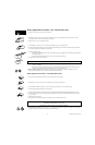
Input Hardwire Instructions
Note:
This function must be performed by qualified personnel only
1. Disconnect and remove the input plug.
2. Remove additional length of outer jacket from cable to ease wire installation.
3. Install cable into electrical box that supplies 30 Amps at 100 Volts. Use a suitable cable clamp.
4. Connect black and white wires to 100V source. (White is connected to neutral - if one of the connectors is identified as neutral.)
5. Connect green wire to ground wire (if present). Otherwise, connect to the metal electrical box.