


Magnum VS –48 Vdc User Manual Page 20
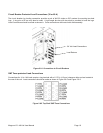
2.10. Rectifier Module Installation
WARNING: Rectifier output DC circuits will be damaged if the batteries are installed
incorrectly. Before installing additional rectifiers, ensure proper battery polarity, and
that the battery is isolated from the rest of the system.
The Magnum VS system includes one (1), 10A, rectifier module. To install additional rectifier modules
(shipped separately), follow the procedure outlined below. Rectifiers are “hot-swappable”, and, hence,
may be installed when the DC system is turned on and in service.
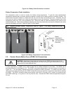
1) Remove the rectifier from its shipping container.
2) Slide the rectifier module into the shelf between the guides until it is fully seated.
3) Secure the rectifier in place with the captive rectifier retaining screws.
Since all system settings are made from the system controller, no physical rectifier settings or adjustments
are necessary.
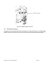
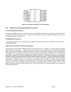
2.11. Controller Module Installation
The Magnum VS Controller Module is installed at the factory. In the Magnum VS 50, the Controller Module is
installed in the right-most slot of the power system. In the Magnum VS 100, the Controller Module is installed in the
upper right-hand slot of the power system.
CAUTION: The controller and the network management card have lithium batteries. These
batteries are not field serviceable.
• Danger of explosion if battery is replaced by an incorrect type.
• Dispose of used batteries according to the manufacturer’s instructions.