


Magnum VS –48 Vdc User Manual Page 26
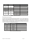
System Current Monitor
The controller monitors individual rectifier currents and displays total system current as a sum of rectifier currents.
Load current can be found by adding battery current to system current. Battery Current is positive when the battery
is discharging.
Sys Current + Batt current = Load Current
For example, if the battery is charging the Batt Current reading could be (–) 10 A, Sys Current reading could be 50
A. Load Current would be:
Sys Current + Batt current = Load Current
50 A + (-) 10 A = 40 A.
If the battery is discharging the Batt Current reading could be 10 A, Sys Current reading could be 30 A. Load
current would be:
Sys Current + Batt current = Load Current
30 A + 10 A = 40 A.
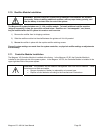
System Status and Alarm Reporting
The controller will monitor system, temperature. The controller reports system high and low temperature alarms.
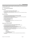
4.3. Load Management
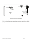
Circuit Breakers
The Magnum VS Distribution Module includes two (2) 30A or one (1) 60A circuit breaker, or eight (8) GMT fuses.
When a circuit breaker trips, a normally open switch closes and the Controller reports a CB alarm. Alarms are
reported only when a breaker is tripped. When a breaker is turned off, no alarm is generated. Circuit Breaker
Alarms 1 or 2 are reported when a circuit breaker in the top shelf trips. Circuit Breaker Alarms 3 or 4 are reported
when a circuit breaker in the bottom shelf trips. Please note that if a Magnum VS 100 system has one (1) circuit
breaker in the top shelf and one (1) circuit breaker in the bottom shelf, the circuit breakers in the bottom shelf will be
labeled CB2 on the front panel, but Circuit Breaker Alarm 3 will be reported. To disconnect a load attached to a
circuit breaker, move the lever down to the “OFF” position.