


2–8
DC Power
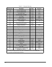
The power connector J10 is a 7-pin polarized connector. Refer to Table 2– 3 for power connections
and Table 2– 4 for mating connector information.
Caution
Be sure the power plug is wired correctly before applying power to the
board! See Table 2– 3.
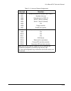
Table 2– 3. Power Connector (J10)
Pin Signal Name Function
1, 7 +5VDC +5VDC ±5% input
2, 3, 6 Ground Ground return
4 +12VDC +12VDC ±5% input
5 +3.3VDC +3.3V ±5% input
(Only required for some PCI expansion boards)
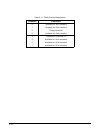
Table 2– 4. J10 Mating Connector
Connector Type Mating Connector
DISCRETE WIRE MOLEX HOUSING 09-50-8073
Pins 08-52-0071
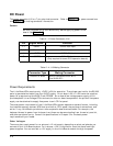
Power Requirements
The Little Board/P5
x
requires only +5VDC (±5%) for operation. The voltage required for the RS-232
ports is generated on-board from the +5VDC supply. An on-board +5V to +12V converter supplies
power for programming the BIOS Flash EPROM. An on-board low-voltage power supply circuit
provides power to low-voltage CPUs and certain other on-board components. An optional Vee power
supply can be attached to supply Vee power to an LCD flat panel.
The exact power requirement of the Little Board/P5
x
system depends on several factors, including
the installed memory devices, SCSI bus termination, CPU speed, the peripheral connections, and
which, if any, MiniModule products or other expansion boards are attached. For example, the
keyboard draws its power from the board, and there can be some loading from the serial, parallel,
and other peripheral ports. Consult the specifications in Chapter 3 for the basic power
requirements of your model.
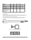
Other Voltages
There may be a requirement for an external +12 volt supply, depending on what peripherals you
connect to the Little Board system. For instance, +12V is required for most flat-panel backlight
power supplies. You can connect a +12V supply to the Little Board module through the power