


Little Board/P5
x
Technical Manual
2–27
Please refer to the IEEE-1284 standard for the complete list of requirements for a compliant cable
assembly, including recommended connectors
Latch-Up Protection
The parallel port incorporates chip protection circuitry on some inputs, designed to minimize the
possibility of CMOS “latch up” due to a printer or other peripheral being powered up while the
Little Board/P5
x
is turned off.
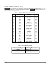
Parallel Port Registers
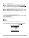
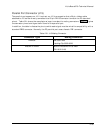
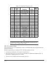
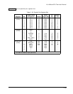
The low-level software interface to the parallel port consists of eight addressable registers. The
address map of these registers is shown in Table 2– 21.
Table 2– 21. Parallel Port Register Map
Register Name
Address
Data Port Base address
Status Port Base address + 1
Control Port Base address + 2
EPP Address Port Base address + 3
EPP Data Port 0 Base address + 4
EPP Data Port 1 Base address + 5
EPP Data Port 2 Base address + 6
EPP Data Port 3 Base address + 7
Note: EPP registers are only accessible when in
EPP mode
Standard and Bi-Directional Operation
You can use the parallel port as a standard output-only printer port or as a PS/2-compatible bi-
directional data port with up to 12 output lines and 17 input lines. The bi-directional mode can be
very valuable in custom applications. For example, you might use it to control an LCD display, scan
keyboards, sense switches, or interface with optically isolated I/O modules. All data and interface
control signals are TTL-compatible.
Set the parallel port’s default mode using Setup.
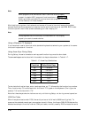
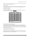
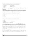
Using the Parallel Port in Bi-Directional Mode
To use the port as a bi-directional data or digital control port you must set the default mode to bi-
directional in Setup or put it in bi-directional mode with a BIOS call. The following code example
shows how to set the parallel port mode to bi-directional.