


Little Board/P5
x
Technical Manual
2–35
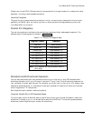
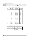
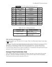
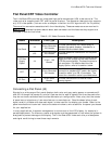
Table 2– 27 (cont.). IDE Interface Connectors (J12, J17)
Pin Signal Name Function In/Out
30 GND Ground OUT
31 HOST IRQ14 Drive interrupt request IN
32 IDE16 IOCS16 OUT
33 HOST A1 Drive address 1 OUT
34 RSVD Reserved N/C
35 HOST A0 Drive address 0 OUT
36 HOST A2 Drive address 2 OUT
37 HOST CS0* Chip select OUT
38 HOST CS1* Chip select OUT
39 RSVD Reserved N/C
40 GND Ground OUT
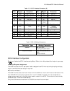
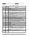
Table 2– 30. J12, J17 Mating Connectors
Connector Type Mating Connector
RIBBON, 40 wire 3M 3417-7600
Latching Clip 3505-8040
DISCRETE WIRE MOLEX HOUSING 22-55-2402
PIN 16-02-0103
IDE Interface Configuration
Use Setup to specify your IDE hard disk drive types. Refer to the Setup section beginning on page
2–62 for details.
If you do not find a drive type whose displayed parameters match the drive you are using, use drive
type USER. It allows you to manually enter the drive’s parameters. The drive manufacturer
provides the drive parameters—check the drive’s documentation for the proper values to enter.
If you are using a newer IDE drive, use drive type AUTO. It automatically configures the drive type
parameters from information provided by the drive itself.
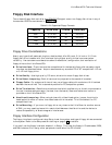
Compact Flash Solid-State Disk
The Little Board/P5
x
connector J23 supports a Compact Flash device, a solid-state IDE hard-disk
emulator. It acts as a removable hard-disk drive. You can format, read, and write the Compact
Flash device much as you would a standard IDE drive.