


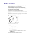

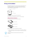
Wiring and Installation
9
I
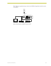
R Sensors and Receivers
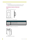
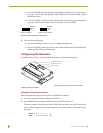
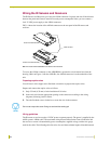
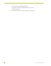
As an example, the DIP switch in FIG. 12 defines device number 129 (1+128=129).
If you later change the device number, remove and reconnect the AXlink connector. This
enters the new device number into memory.
3. Go on to Setting the IR Validation Level below.
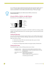
Setting the IR Validation Level
An IR transmitter must send repetitions of data for the receiver to accept it as valid data. In some
installations, a light wall color or other physical condition may interfere with the sensor's or
receiver's ability to sense the transmitted signal. The signal may reflect or bounce and become
distorted. The receivers can be set to use either two or three repetitions of sequential signals to
validate and accept the signal data.
Receiver IR validation level
Perform the following steps to set the receiver's IR level.
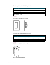
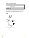
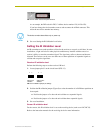
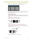
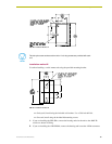
1. Locate jumper pins J1 on the circuit board (FIG. 13).
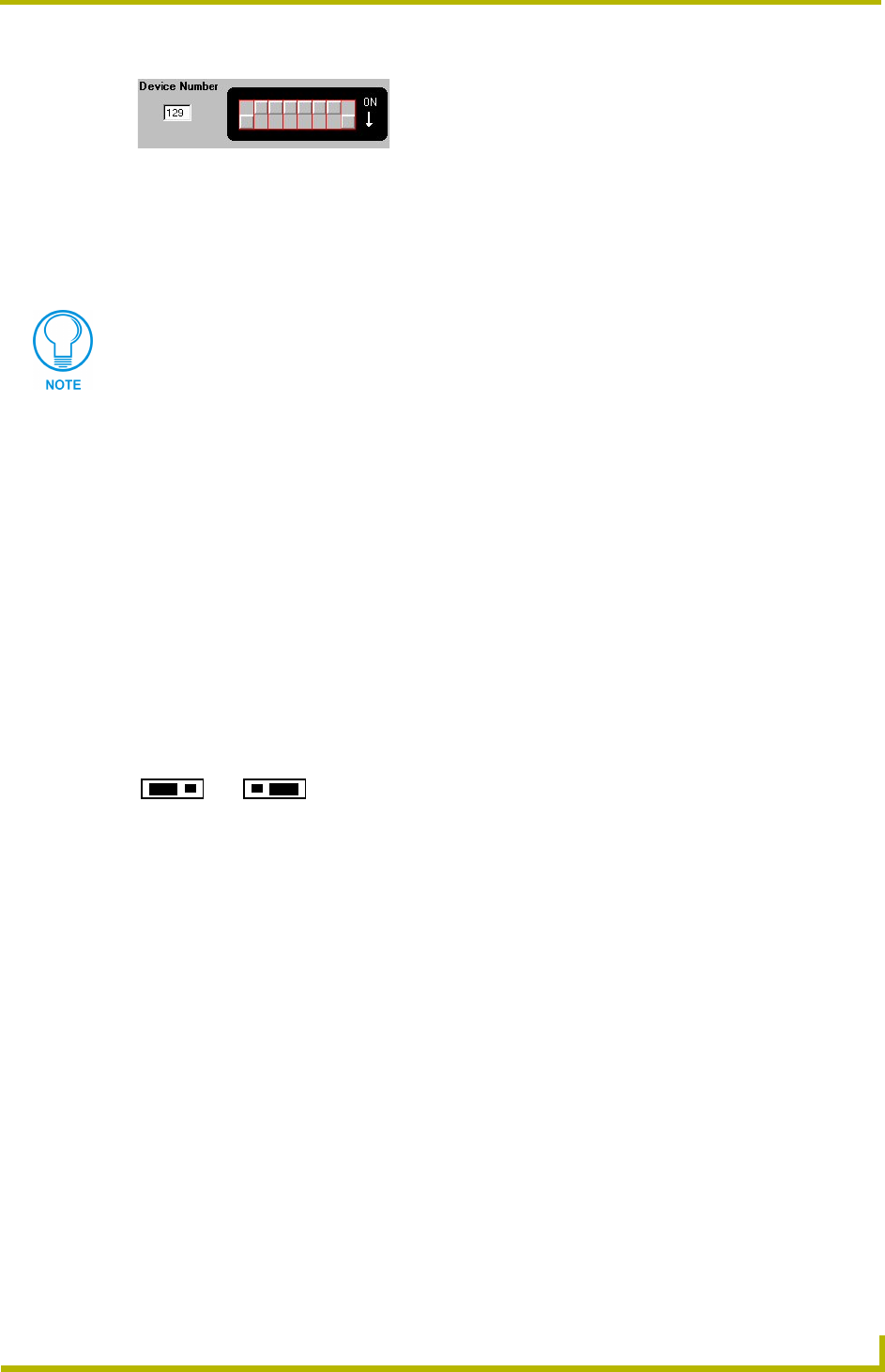
2. Position the IR validation jumper (Figure 9) to select the number of valid IR data repetitions to
be accepted:
!
Position the jumper at 2 to have the unit validate two sequential signals.
!
Position the jumper at 3 to have the unit validate three sequential signals.
3. Go on to Installation.
Sensor IR validation level
For the sensors, this IR validation level is set on the receiving device (such as an AXC-RCVI).
Refer to the instruction manuals for the receiving device for more information.
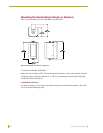
FIG. 12 DIP switch values and quick reference
The device number takes effect only on power-up.
FIG. 13 IR validation jumper pin settings
32
J1
32
J1
Setting for two
validations
Setting for three
validations