


Wiring and Installation
11
I
R Sensors and Receivers
the receiver or sensor and the Central Controller. The maximum wiring lengths are based on a
minimum of 13.5 volts available at the Central Controller's power supply.
If you install the IR sensor or receiver farther away from the Central Controller than recommended
in the Wiring Specifications table, connect an external 12 VDC power supply, as shown in the
wiring diagrams in this section.
Connecting the Wiring
The following paragraphs describe wiring connections using AXlink for data and power, using
AXlink plus an external 12 VDC power supply, and wiring the IRX-DM+ or IRX-SM+ to the AMX
IR receiver.
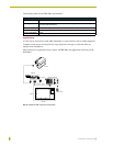
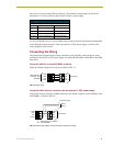
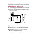
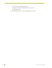
Wiring the AXD-IR+ or the AXR-IRSM+ to AXlink
Install the AXlink data/power bus wiring as shown in FIG. 15.
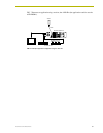
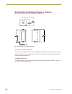
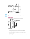
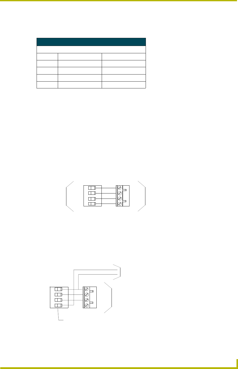
Using the AXlink four-pin connector with an external 12 VDC power supply
Connect the Central Controller's AXlink connector to the AXlink connector on the AXD-IR+ or the
AXR-IRSM+ as shown in FIG. 16.
Wiring Specifications
Maximum Wiring Length
Wire Size IR Sensors IR Receivers
18 AWG 4,696 feet (1431.34 m) 3,354 feet (1022.30 m)
20 AWG 2,970 feet (905.26 m) 2,121 feet (646.48 m)
22 AWG 1,851 feet (564.18 m) 1,314 feet (400.511 m)
24 AWG 1,167 feet (355.70 m) 833 feet (253.90 m)
FIG. 15 AXlink wiring
FIG. 16 AXlink wiring diagram using an external 12 VDC power supply
1
3
2
4
GND
(
-
)
AXP
AXM
PWR (+)
(
-
)
GN
D
AXP
AXM
(+) PW
R
1
3
2
4
AXlink connector on
the AXD-IR+ or the
AXR-IRSM+
Control system
12 VDC power supply
Control system
1
3
2
4
GND
(
-
)
AXP
AXM
PWR (+)
1
3
2
4
PWR
(
+
)
GND
(
-
)
(
-
)
GN
D
AXP
AXM
(+) PW
R
AXlink connector on the AXD-IR+
or the AXR-IRSM+