


Wiring and Installation
13
I
R Sensors and Receivers
If the LED is on and not flashing, disconnect the AXlink connector and recheck all AXlink
connections. Afterward, reconnect the AXlink connector to the panel and verify the LED is flashing
once per second.
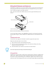
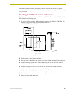
Mounting the UniMount Sensor or Receiver
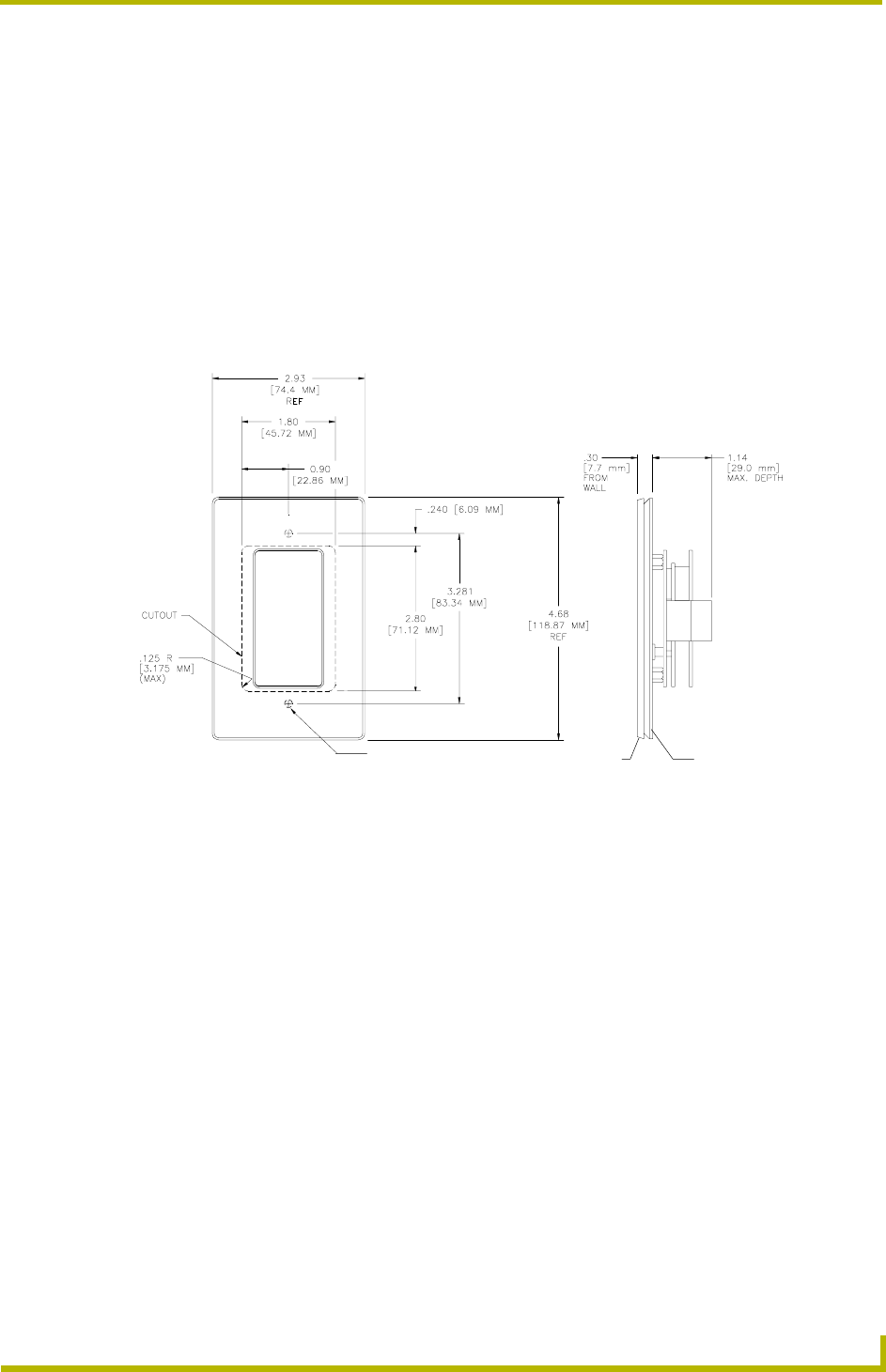
FIG. 18 gives cutout dimensions for the AXD-IR+ and IRX-DM+. To install the AXD-IR+ or IRX-
DM+, complete the following steps.
1. For wall or podium mounting, AMX recommends mounting the AXD-IR+ or IRX-DM+ in a
standard 1-gang wallbox with a minimum internal clearance of
1 3/4" (W) x 2 5/8" (H) x 1 5/8" (D).
2. Gently remove the bezel from the wallplate.
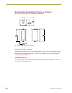
3. Place the panel in the wallbox and align the screw holes with the mounting holes on the panel.
4. If you are installing the IRX-DM+, remove the housing and wire the unit to the AMX IR
receiver as shown in Wiring.
5. If you are installing the AXD-IR+, turn the unit over and locate the AXlink connector.
a. Connect the unit to AXlink data/power bus. See Wiring.
b. Check the AXlink LED. (LED should blink once per second.)
6. Fasten the panel to the wallbox using the screws supplied with the panel.
7. Snap the wallplate back on the bezel.
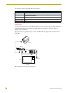
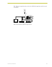
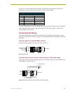
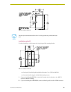
FIG. 18 AXD-IR+ and IRX-DM+ 1-gang cutout dimensions
INSTALL UNIT USING
SUPPLIED #6-32
MACHINE SCREWS AT
THESE LOCATIONS
Wall plate Bezel