


Wiring and Installation
10
IR Sensors and Receivers
Wiring the IR Sensors and Receivers
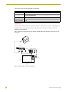
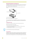
The IR Sensors and Receivers use a four-pin AXlink connector for power and data. If the distance
between the panel and Central Controller exceeds power consumption limits, you can connect a
local 12 VDC power supply to the AXlink connector.
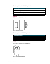
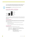
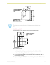
FIG. 14 shows the location of the AXlink connector on the rear panel of the IR sensors and
receivers.
To access the AXlink connector on the AXR-IRSM+, separate the swivel-mount base from the
housing. (Refer to Figure 4.) On the AXD-IR+, the AXlink connector is on the underside of the
unit.
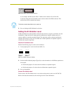
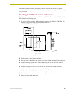
Preparing captive wires
You will need a wire stripper and a flat-blade screwdriver to prepare the captive wires.
Prepare and connect the captive wires as follows.
1. Strip .25 inch (6.35 mm) of wire insulation off all wires.
2. Insert each wire into the appropriate opening on the connector according to the wiring
diagrams (following) in this section.
3. Turn the flat-head screws clockwise to secure the wire in the connector.
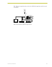
Wiring guidelines
The IR sensor or receiver requires 12 VDC power to operate properly. The power is supplied by the
AMX system's AXlink cable. The maximum wiring distance between the Central Controller and
the receiver or sensor is determined by power consumption, supplied voltage, and the wire gauge
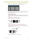
used for the cable. The following table lists wire sizes and the maximum lengths allowable between
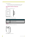
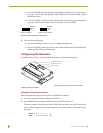
FIG. 14 Circuit board assemblies for IR sensors and receivers
Sensor circuit board assembly
AXlink connector
Receiver circuit board assembl
y
Do not over-torque the screw. Doing so can bend the seating pin