


Introduction
5
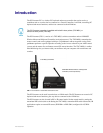
PC Presenter
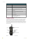
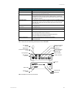
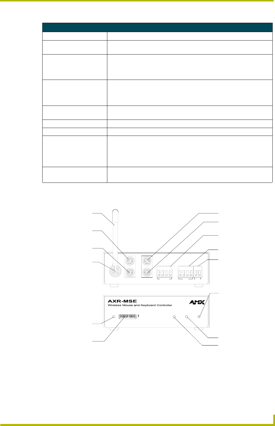
FIG. 5 shows the rear and front panel features of the AXR-MSE.
AXR-MSE Specifications (Cont.)
Rear Panel
TNC RF antenna Accepts the flexible RF receiving antenna (up to 6 feet of RG-58 coax cable for
remote antenna set up can also be used).
KEYBOARD IN/OUT Two PS/2 style keyboard connectors are used to connect the AXR-MSE to the
PC keyboard and CPU. The top connector, labeled "TO PC" connects the
AXR-MSE to the CPU with a PS/2 style cable (included). Plug the PC keyboard
into the bottom connector.
MOUSE IN/OUT Two PS/2 style mouse connectors are used to connect the AXR-MSE to the PC
mouse and CPU. The top connector, labeled "TO PC" connects the AXR-MSE
to the CPU with a PS/2 style cable (included). Plug the PC mouse into the
bottom connector.
External IR Sensor
connector
4-pin data/power captive-wire is used to connect an optional external IR sensor
(for IR applications).
AXlink connector 4-pin data/power captive-wire.
Power connector Optional 2-pin +12V power captive-wire.
Included accessories • 800 mA power supply @ 12 VDC
• Two PS/2-style cables, male to male (6 ft.)
• Two 4-pin captive-wire connectors (for AXlink and IR sensor)
• One 2-pin captive-wire connector (for power)
Optional accessories • 315 MHz and 433.9 MHz RF frequencies are available
• External IR sensor
FIG. 5 AXR-MSE rear and front panel features
MOUSE
DEVICE
AXlink
ON
KEYBOARDANTENNA
PC
TO
KEYBOARDMOUSE DATA
AXlink
IR IN
EXTERNAL
IR SENSOR
AUX
PWR
GND
AXM
GND
PWR
IN
GND
PWR
AXP
+12VDC
RF receiving
antenna
Keyboard out
(to keyboard connector
on PC)
PC Keyboard in
TNC antenna
connector
AXlink LED
DEVICE DIP
switch
Mouse out (to mouse
connector on PC)
PC Mouse in
Optional external IR
sensor connector
(455 KHz only)
AXlink connector
+12VDC connector
Data LED
Keyboard LED
Mouse LED