


Using the Power Sensor Making Measurements
MA24106A UG 3-11
3-8 Making Measurements
This section presents common procedures for using the MA24106A power sensor. These procedures refer to the
MA24106A buttons and menus that were previously described. You should be familiar with the Anritsu Power
Meter PC application before attempting these procedures.
Basic Power Measurement
To perform a power measurement:
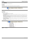
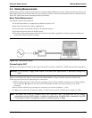
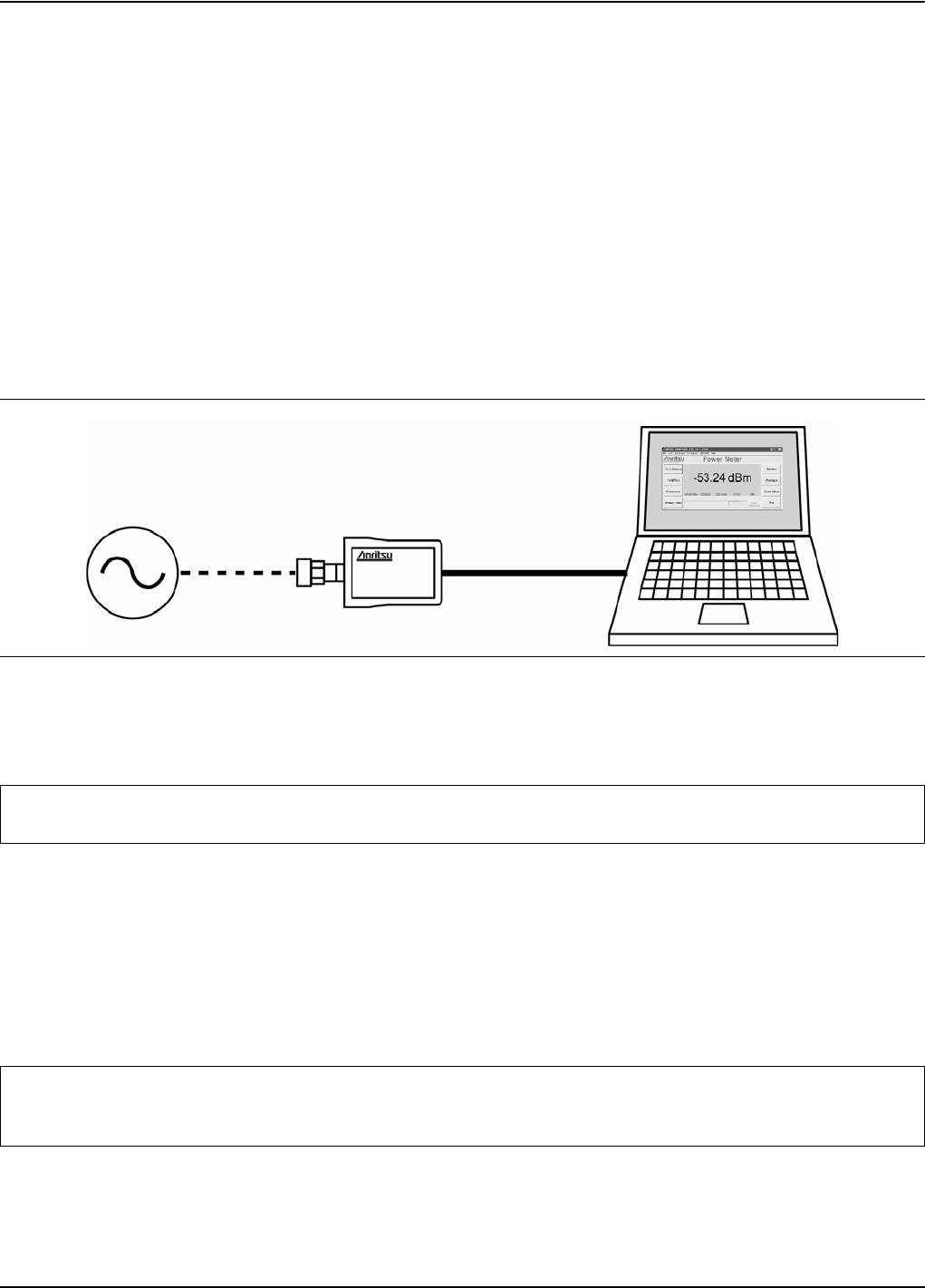
1. Connect the sensor to a computer as shown in Figure 3-19.
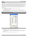
2. Open the Anritsu Power Meter application.
3. Zero the sensor as described below in Zeroing the Sensor.
4. Connect the power sensor to an RF source.
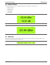
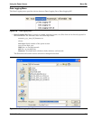
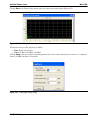
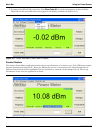
5. Read the power measurement from the Anritsu Power Meter application window (power readings are
continuous with the default setting).
Connecting the DUT
RF signal connections are made to the Type N male RF connector, which has a 50 Ω characteristic impedance.
When connecting to the Type N connector of the MA24106A to a Type N female connector, observe the
following proper practice for tightening the connection:
1. While holding the body of the sensor in one hand, turn the Type N Male connector nut to finger tighten
the connection. Do not turn the body of the MA24106A as this will cause excessive wear to the
connector.
2. Back off the connection by turning the connector nut counter clockwise ¼ turn.
3. Tighten the connection (clockwise) using a 12 in-lb torque wrench (Anritsu part number: 01-200).
Figure 3-19. Measurement Setup
Warning: Do not connect or apply power outside of the MA24106A specifications or permanent damage may
result.
Note: The Sensor has a USB 2.0 interface with a USB Type Mini-B port. The MA24106A can be remotely
programmed over this USB interface. In addition to programming, the MA24106A is powered by the USB.
The interface is USB 2.0 compatible, but with an interface speed of 12 Mbps.