


Sensor Operational Tests Calibration Factor Test
MA24106A UG 5-3
5-4 Calibration Factor Test
In this test the calibration factors of the MA24106A are compared against another sensor (referred to in this
procedure as the “reference sensor”) with known calibration factor uncertainties. This reference sensor should
be calibrated by a reputable standards laboratory which has low published measurement uncertainty. To
perform the comparison, both sensors are used to measure the output power of a synthesizer with a high
quality attenuator, such as the 41KC-6, on the output. The attenuator improves the source match of the
synthesizer by lowering the mismatch ripples, thereby lowering the uncertainty in the comparison.
Test Procedure
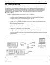
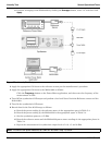
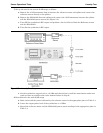
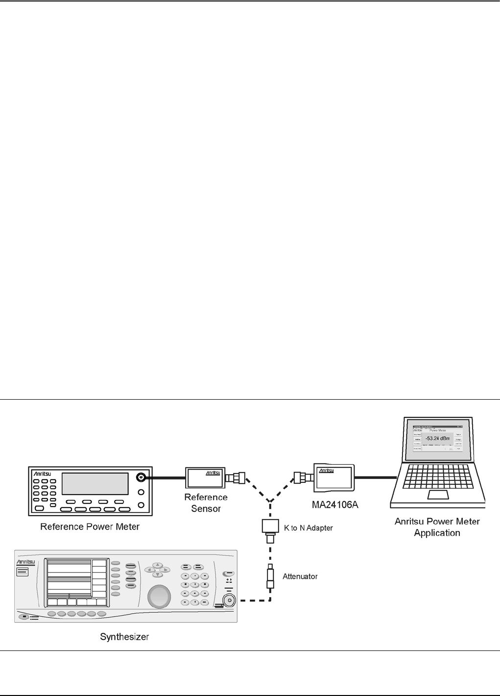
1. Set up the equipment as follows (refer to Figure 5-1 for an illustration):
a. Connect the reference power sensor to the reference power meter using the appropriate cables.
b. Connect the MA24106A USB cable between the personal computer with the Power Meter
application installed and the MA24106A power sensor under test.
c. Launch the Power Meter application.
d. Turn the power on to all of the instruments and allow them to warm up for the amount of time
specified in their respective manuals.
e. Reset or Preset all of the instruments.
f. Configure the reference meter and sensor to measure a CW signal.
g. Perform a sensor Zero and a 1 mW reference calibration on the reference sensor and meter per the
manufacturer’s instructions.
h. Perform a low level Zero of the MA24106A as follows:
With the MA24106A disconnected from the synthesizer, click the Zero Sensor button on the
Power Meter application and wait for the Zeroing Sensor message to close.
i. Connect the attenuator to the output of the synthesizer with the appropriate adapter to the output
of the attenuator.
j. Set the synthesizer to +6 dBm and 50 MHz.
Figure 5-1. Cal Factor Test Set Up