


Linearity Test Sensor Operational Tests
5-6 MA24106A UG
n. Increase averaging on the MA24106A by clicking the Averages button, enter “16” and then click
Apply.
2. Apply the appropriate Cal factor to the reference sensor per the manufacturer’s procedure.
3. Apply the appropriate Cal factor to the MA24106A as follows:
Click the Frequency button on the Power Meter application, and then enter the frequency of the
measurement in GHz.
4. Turn Off the synthesizer’s RF output and perform a low-level Zero of both the Reference sensor and the
MA24106A.
5. Turn On the synthesizer’s RF output.
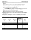
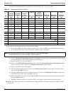
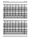
6. Record data for the first 20 dB range as follows:
a. Record the power reading by the reference meter in the appropriate space in Table 5-4.
b. Record the power reading by the MA24106A in the appropriate space in Table 5-4.
c. Set the synthesizer power to +15 dBm.
d. Record the reference meter and the MA24106A power sensor readings in the appropriate places in
Table 5-4.
e. Repeat the measurement for synthesizer output levels of +10, +5, and 0 dBm.
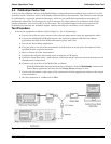
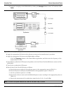
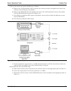
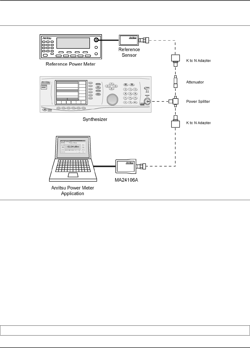
Figure 5-2. Linearity Test Setup
Note: The MA24106A power measured at 0 dBm will be used in step 7e, below.