


21
Pin
Signal
Names
(HDA)
Pin
Signal
Names
(AC’97)
1
MIC2
L
1
MICIn
2
AGND
2
GND
3
MIC2
R
3
MICPower
4
AVCC
4
N
C
5
FRO-R
5
Line
Out
(R)
6
MIC2_JD
6
Line
Out
(R)
7
F_IO_SEN
7
N
C
8
Key(nopin)
8
Key(nopin)
9
FRO-L
9
Line
Out
(L)
10
LINE2_JD
10
Line
Out
(L)
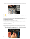
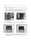
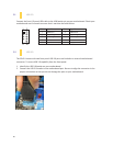
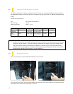
3.3 AC’97
/
HD
A
UDIO
P
ORTS
There is an Intel
®
standard 10-pin AC’97 connector and an Intel® 10-pin HDA (High Definition Audio)
connectorlinked to the front panel of the chassis.
You can connect either the AC’97 or the HDA connector, depending on your motherboard. Locate
the internal audio connectors from your motherboard or sound card and connect the corresponding
audio cable. Consult your motherboard or sound card manual for the pin-out positions. Even if your
system supports both standards, only use one connector
.
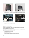
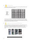
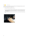
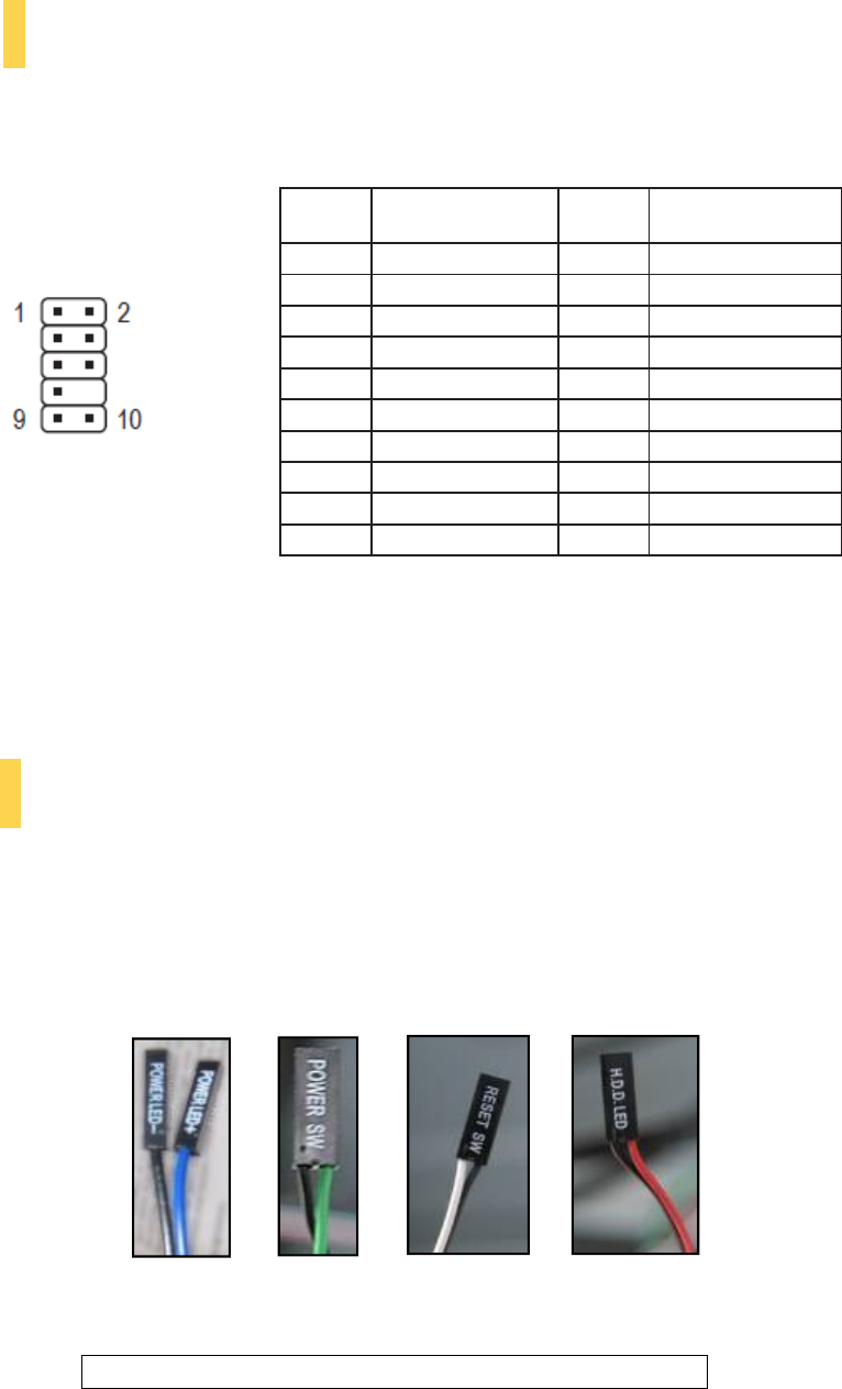
3.4 P
OWER
S
WITCH
/
R
ESET
S
WITCH
/
H
ARD
D
ISK
D
RIVE
LED
C
ONNECTORS
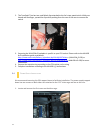
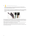
Connected to your front panel are LED leads for power and HDD activity, as well as switch leads for the power
and reset buttons. Attach these to the corresponding connectors on your motherboard. Consult your
motherboard manual for specific pin header locations. For LEDs, colored wires are positive ( + ). White or black
wires are negative ( – ). If the LED does not light up when the system is powered on, try reversing the
connection. For more information on connecting LEDs to your motherboard, see your motherboard user’s
manual.
Note: Polarity (positive and negative) does not matter for switches.
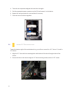
Front panel leads