


990-7031D, Revision 5 5/01
9
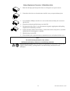
With the UPS plugged in, press and release the large upper on/test button to supply power to the loads. The loads are
immediately powered while the UPS beeps and performs a self-test.
Press and release the small, lower off button to turn off power to the loads. It may be convenient to use the UPS as a
master on/off switch for the protected equipment.
Note:
Whenever the UPS is plugged in and utility voltage is present, the charger maintains battery charge.
The on-line LED illuminates when the UPS is supplying utility power to the loads.
On Battery
During on-battery operation, the on-battery LED illuminates and the UPS sounds an audible alarm consisting of four beeps
every 30 seconds. The alarm stops when the UPS returns to on-line operation.
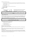
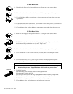
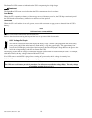
Battery Charge Bar Graph
The 5-LED display on the right of the front panel shows the present charge of the UPS’s battery as a percentage of
the battery’s capacity. When all five LEDs light, the battery is fully charged. The top LED goes out whenever the
battery is not 100% charged. When the lowest LED is flashing, the battery can supply less than two minutes of
run time for the load. The battery capacity threshold is shown in the figure to the left (values are not listed on the
UPS).
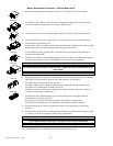
Shutdown Mode
In shutdown mode the UPS stops supplying power to the load, waiting for the return of utility power. If there is no
utility power present, external devices (e.g., servers) connected to the computer interface or the accessory slot can
command the UPS to shut down. This is normally done to preserve battery capacity after the graceful shutdown of
protected servers. The UPS will scroll the front panel indicators sequentially in shutdown mode.
Self-test
The UPS performs a self-test automatically when turned on, and every two weeks thereafter (by default). Automatic self-
test eases maintenance requirements by eliminating the need for periodic manual self-tests.
During the self-test, the UPS briefly operates the loads on-battery. If the UPS passes the self-test, it returns to on-line
operation.
If the UPS fails the self-test it immediately returns to on-line operation and lights the replace battery LED.
The loads are not affected by a failed test. Recharge the battery overnight and perform the self-test again. If the replace
battery LED is still on, replace the battery using the procedure in Replacing the Battery, page 11.
Replace Battery
If the battery fails a self-test, the UPS emits short beeps for one minute and the replace battery LED illuminates. The UPS
repeats the alarm every five hours. Perform the self-test procedure to confirm replace battery conditions. The alarm stops
when the battery passes the self-test.
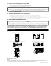
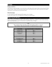
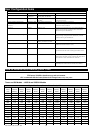
Load Bar Graph
85%
67%
50%
33%
17%
The 5-LED display on the left of the front panel represents the power drawn from the UPS as a percentage of total
capacity. For example, if three LEDs are lit, the load is drawing between 50% and 67% of the UPS’s capacity. If all
five LEDs light, thoroughly test your complete system to make sure that the UPS will not become overloaded. In
the graph to the left the load capacity threshold is listed next to the LED (values are not listed on the UPS).
Overload
When the UPS is overloaded (the connected loads exceed the maximum specified in the “maximum load” section under
Specifications, page 19), the overload LED comes on and the UPS emits a sustained tone. The alarm remains on until the
overload is removed. Disconnect nonessential load equipment from the UPS to eliminate the overload.
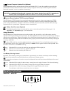
SmartTrim
100%
80%
60%
40%
20%