


UPS Connections
Electrical connections and cabinet interconnection will vary depending upon the conguration and
options selected with your MGE Galaxy 4000 UPS system. Refer to the installation drawings supplied
with your equipment.
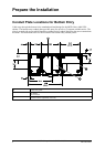
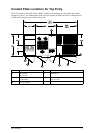
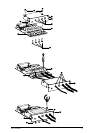
Connecting Power Cable Connections:
To access the connection terminal blocks, open the right door to the MGE Galaxy 4000 UPS. Remove
the safety panel located in the lower right hand section of the unit. See “Typical Power Connections“.
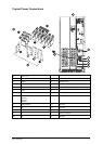
1. The ground and neutral conductors must be connected to the ground and neutral busbars,
respectively. The input and output neutral are connected at the neutral busbar.
2. Connect the three conductors of the main AC source to terminal block TB1.
3. If bypass source is present, connect the conductors of the bypass AC source to terminal block
TB3. If bypass source is not present, verify jumpers in place between TB1 and TB3.
4. Connect the three conductors supplying the load to terminal block TB2.
5. Connect the battery conductors to the positive and negative busbars.
6. Secure all cables with cable ties.
7. Put all panels and covers back in place.
Main AC Input Connections
The connections to be made are the three phases, neutral, and ground cables from the utility AC power
source to the UPS. The main AC input cables are terminated at the main input terminal block (TB1).
See “Typical Power Connections“.
Note: For single input (optional conguration), jumper cables are provided from
terminal blocks TB1 to TB3.
Bypass AC Input Connections (optional)
The bypass AC input cables are terminated at the bypass input terminal block (TB3). This option
provides a separate AC input source for bypass operation. See “Typical Power Connections“.
12
MGE Galaxy 4000 40–75 kVA 208 V
990–3964–001