


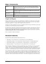
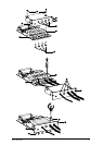
Connect Relay Communication Card
Relay Communication Card Contacts
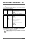
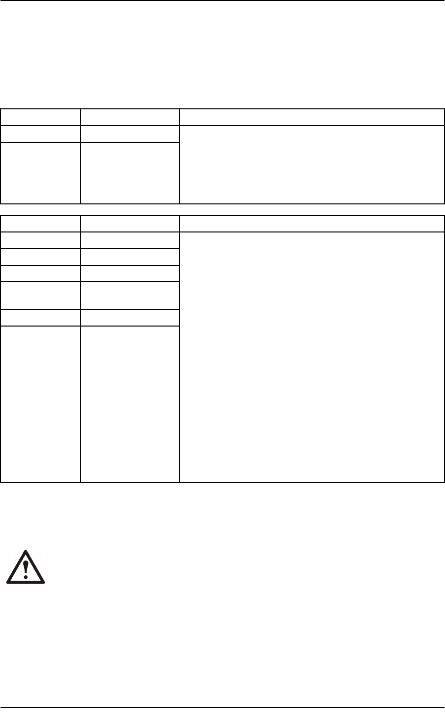
The relay communication card contains six programmable dry contact outputs and two programmable
dry inputs and is standard on the MGE Galaxy 4000. The inputs and outputs are factory programmed
according to functions listed in table below.
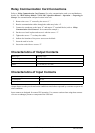
Inputs
Factory Settings
Options (available on both contacts)
1.A UPS ON
1.B UPS OFF
• Room temperature fault
• Transfer to bypass disabled
• Transfer to bypass disabled if bypass AC source out of
tolerance
• Desynchronize UPS from bypass AC source
Outputs Factory Settings
Options (available on all contacts)
1.1
General alarm
1.2
Battery fault
1.3
Load on UPS
1.4
Load on automatic
bypass
1.5
Load on battery power
1.6
Low battery warning
• Overload
• PFC Fault
• Inverter fault
• Charger fault
• Automatic bypass fault
• Bypass AC source out of tolerance
• Battery-temperature fault
• Emergency power off activated
• Battery circuit breaker(s) open
• Phase-sequence fault on normal or bypass
• AC source
• Blown fuse(s)
• Transfer to bypass AC source disabled
• Operation in ECO mode
• UPS on bypass AC source
The output contacts numbers for a second relay board installed will be 2.1 to 2.6. Contacts are of
the NO (normally open) type. For dry contacts setting see “MGE Galaxy 4000 40–75 kVA 208 V
Operation Manual — User Conguration — Settings Screen“.
Caution: Isolate and lock-out all power sources for this card before making connections.
Never connect ELSV (extra low safety voltage) and non-ELSV circuits to the different
outputs of the same card.
16
MGE Galaxy 4000 40–75 kVA 208 V
990–3964–001