


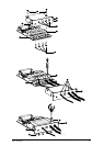
Relay Communication Card Connections
Refer to “Relay Communication Card Contacts“ for relay communication card, cover and hardware
details. See “MGE Galaxy 4000 40–75 kVA 208 V Operation Manual — Operation — Preparing for
Startup“ for communication card port location in the unit.
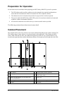
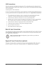
1. Remove the cover “3” secured by the screws “1”.
2. Run the communication cables through the cable entry holes “4”.
3. Connect the conductors to the input “6” and output “5” terminal blocks (refer to “Relay
Communication Card Contacts“ for a connection example.)
4. Put the cover back in place and secure it with the screws “1”.
5. Tighten the screws “7” to clamp the cables.
6. Indicate the locations of the power sources on the labels.
7. Insert the card in its slot.
8. Secure the card with two screws “2”.
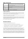
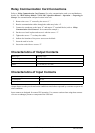
Characteristics of Output Contacts
Relay Type Normally Open
Max. voltage
250VAC, 30VDC
Max. current
2 A
Cable
4 x 0.93 mm, 6.6 ±0.3 mm
Characteristics of Input Contacts
Switched voltage
5VDC
Consumption
10 mA
Cable
4 x 0.34 mm, 5 ±0.5 mm
Output alarms are always activated on the conditions stated unless requested by customer to operate on
other conditions.
Input contacts are designed for remote UPS operation. Use extreme caution when using these contacts
so as not to endanger persons or compromise the UPS load.
18
MGE Galaxy 4000 40–75 kVA 208 V
990–3964–001