


34001813EN/AE - Page 27
2. Installation
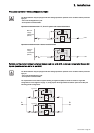
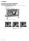
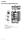
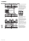
UPS units with separate normal and Bypass AC inputs
To access the connection terminal blocks,
see section 1.2.
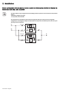
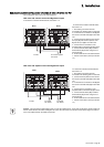
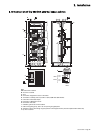
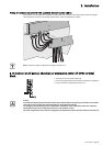
1 - The earthing conductors must be
connected to the earthing plate of each UPS.
2 - Connect the three phases of the Normal
AC source to terminal block (16) in each UPS
unit.
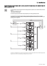
3 - Connect the four conductors of the Bypass
AC source to terminal (61) in the bypass
cabinet.
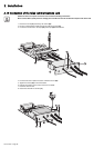
4 - Connect terminal blocks (15) in each UPS
unit to terminal (60) in the bypass cabinet,
using cables with identical lengths and sizes.
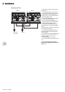
5 - Connect the four load conductors to
terminal (62) in the bypass cabinet.
6 - Connect terminal blocks (14) in each UPS
unit to terminal (63) in the bypass cabinet,
using cables with identical lengths and sizes.
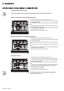
7 - Tie the cables down to the frames of the
UPS cabinets and the bypass cabinet.
8 - Put the covers back in place (see section
1.2).
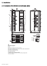
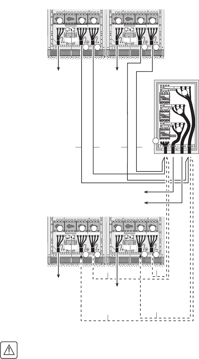
The cables marked A must be identical,
i.e. same size and length.
Similarly, the cables marked B must be
identical, i.e. same size and length.
To avoid errors, it is advised to remove the handle on switch Q3BP (10) in each UPS.
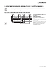
N L1 L2 L3N L1 L2 L3L1 L2 L3
370 mm
N L1 L2 L3N L1 L2 L3L1 L2 L3
370 mm
N L1 L2 L3N L1 L2 L3L1 L2 L3
370 mm
N L1 L2 L3N L1 L2 L3L1 L2 L3
370 mm
14
16
15
14
16
15
Q4S
Q3BP
Q5N
L1
L2
L3
N
L1
L2
L3
N
L1
L2
L3
N
L1
L2
L3
N
60
61
62
63
14
16
15
14
16
15
17
18
17
18
17
18
17
18
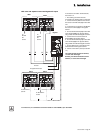
AB AB
A
B
A
B
To
Normal
AC
source
To bypass AC source
To normal AC
/
bypass AC
To normal AC
/
bypass AC
To normal AC
/
bypass AC
To Normal AC
source
To Normal AC
source
To
Normal
AC
source
UPS 1
UPS 2
Bypass
UPS 3
UPS 4
To load