


34001813EN/AE - Page 56
4. Maintenance
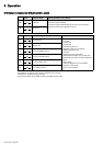
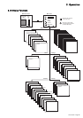
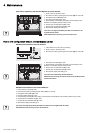
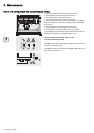
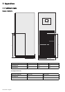
Parallel UPS configuration with external bypass cabinet
1 - Check that all switches on the UPS units are set to OFF.
2 - Set switch Q4S in the external bypass cabinet to ON.
3 - Set switch Q4S (9) on each UPS unit to ON.
4 - Set output switch Q5N (11) on each UPS unit to ON.
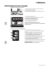
5 - Check that all the UPS units present in the installation are included in
the list on the display and confirm by pressing the function button (35) on
each UPS unit.
6 - Set switch Q5N in the external bypass cabinet to ON.
7 - Set switch Q3BP in the external bypass cabinet to OFF.
8 - Set the input circuit-breaker Q1 (8) on each UPS unit to ON.
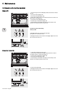
9 - Set the battery circuit-breaker QF1 (13) on each UPS unit to ON (or set
the battery circuit-breakers of the auxiliary cabinets if any)
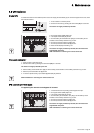
The UPS units start automatically. LED (31) is ON.
The load is protected by the UPS.
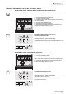
If LED (31) remains OFF, press the ON button (37) on each UPS unit (the
system is in manual start mode).
If LED (31) still remains OFF and either of LEDs (32) or (33) is ON, a fault
has occurred (see section 4.1).
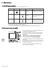
Q1 Q4S Q3BP Q5N
QF1
13
8
10
11
9
IO
3s
?
~
37
31 32 33