


34001813EN/AE - Page 32
2. Installation
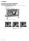
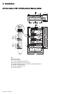
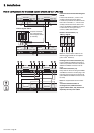
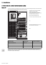
Parallel configuration for increased capacity (maximum four UPS units)
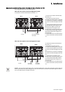
Interconnections with the external bypass
cabinet
◗ Interconnect terminals 1, 3 and 5 on the
auxiliary terminal block in the cabinet.
◗ Create a loop between the cabinet and the
UPS units for terminals 1, 2, 4 and 6 on the
auxiliary terminal block in the cabinet. The
order for the XMS04 and XMS05 connectors
in each UPS unit, from right to left, is
common, Q3BP, Q4S and Q5N.
Details of terminal blocks (11)
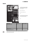
Note. The interconnection cables for the
external bypass cabinet are not supplied
(size 2.5 mm
2
maximum).
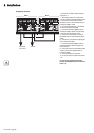
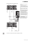
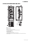
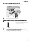
Exchange-current interconnections (10):
Use the XMS02 and XMS03 connectors to
create a loop between the UPS units (all the
XMS02 and XMS03 connectors must be
used).
CAN // interconnections (12):
Daisy-chain the UPS units using the XMS06
and XMS07 connectors. Fit a blue plug on the
first UPS unit and a red plug on the last unit
(all the XMS06 and XMS07 connectors must
be used).
Note. The supplied cables are ten meters
long.
To ensure sufficient isolation of
exchange-current, CAN and external
bypass cabinet cables, they must be run
separately from the power cables
XMS02 XMS03
XMS06 XMS07
XMS04 XMS05
CAN //
XMS02 XMS03
XMS06 XMS07
XMS04 XMS05
CAN //
XMS02 XMS03
XMS06 XMS07
XMS04 XMS05
CAN //
XMS02 XMS03
XMS06 XMS07
XMS04 XMS05
CAN //
Q3BP
Q4S
Q5N
2 3 4 5 61
11
11
11
11
UPS 2
UPS 1
UPS 4
UPS 3
External bypass cabinet
Jumpers connected to
aux. terminal block of
external bypass cabinet
(if necessary)
Blue
plug
Red
plug
XMS 04 / XMS 05
Q4S
Q3BP
Q5N
Common
XMS02 XMS03
XMS06 XMS07
XMS04 XMS05
CAN //
XMS02 XMS03
XMS06 XMS07
XMS04 XMS05
CAN //
XMS02 XMS03
XMS06 XMS07
XMS04 XMS05
CAN //
XMS02 XMS03
XMS06 XMS07
XMS04 XMS05
CAN //
10 10 12 12 10 10 12 12
UPS 1
UPS 2
UPS 4
UPS 3
Blue
plug
Red plug