


Specification guide
Single UPS, three-phase, 160 to 500 kVA
(cont.)
APC by Schneider Electric Edition - 01/2010 Single UPS spec - p.
9
- the remaining battery service life.
ω Display of status conditions and events
It shall be possible to display the following indications:
- Load on battery power
- Load on UPS
- Load on automatic bypass
- General alarm
- Battery fault
- Remaining battery backup time
- Low battery warning
- bypass AC source outside tolerances
- Battery temperature.
Additional information shall be provided in view of accelerating system servicing, as specified in section 11.
ω Display of operating graphs
It shall be possible to display bar graphs of the measurements mentioned above on the screen over significant
periods.
ω Statistics
Number of overloads, number of transfers to battery power, cumulative time on battery power, maximum power
levels, demand power levels.
ω log of time-stamped events
This function shall store in memory and make available, for automatic or manually initiated recall, time-stamped
logs of all important status changes, faults and malfunctions, complete with an analysis and display of
troubleshooting procedures. It shall be possible to time stamp and store at least 2500 events.
10.1.2. Controls
The UPS shall comprise the following controls:
ω two ON and OFF buttons
Located on the front panel of the UPS, they shall control UPS-unit ON/OFF status.
It shall be possible to turn OFF the UPS externally via an isolated dry contact.
ω EPO terminal block
The UPS shall be equipped with an emergency power off (EPO) terminal block for complete system shutdown
following reception of an external control signal. The EPO command shall result in:
- Shutdown of UPS units
- Opening of the static switches on the bypass line and of the battery circuit breaker
- Opening of an isolated dry contact on the programmable card.
ω Alarm reset button
This button shall turn off audio alarms (buzzer) (see section 10.1.3). If a new alarm is detected after clearing the
first, the buzzer sounds again.
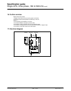
10.1.3. Status indications with mimic panel
Indication of status conditions shall be distinct of the graphic display.
Three LEDs on the control panel indicate the following status conditions:
ω Load protected
ω Minor fault
ω Major fault.
The mimic panel shall represent the UPS and indicate the status of the load supply using five two-color (red and
green) LEDs:
ω Load supplied (LED at UPS output on mimic panel)
ω Inverter on (inverter LED on mimic panel)
ω Operation on battery power (LED between battery and inverter on mimic panel)
ω Bypass activated (bypass LED on mimic panel)
ω PFC rectifier on (rectifier LED on mimic panel).
A buzzer shall warn the user of faults, malfunctions or operation on battery power.
10.2. Communication
10.2.1. Standard communication
It shall be possible to remote the following controls, indications and measurements. To that end, the UPS shall
have as standard equipment:
ω a programmable card with four inputs and six outputs.
10.2.2. Communications options
The UPS shall be designed to enable the extension of communications, without system shutdown, to the following
types of cards:
ω Multi-standard communications card with two outputs:
- an RS485 serial-link implementing the JBus/ModBus protocol for connection to a building management system
(BMS)