


Installation
990-1378
Installation Guide APC BC300 Series 10kW 208/450/480V UPS 11
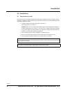
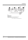
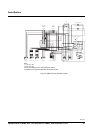
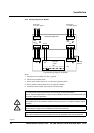
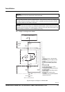
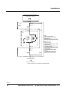
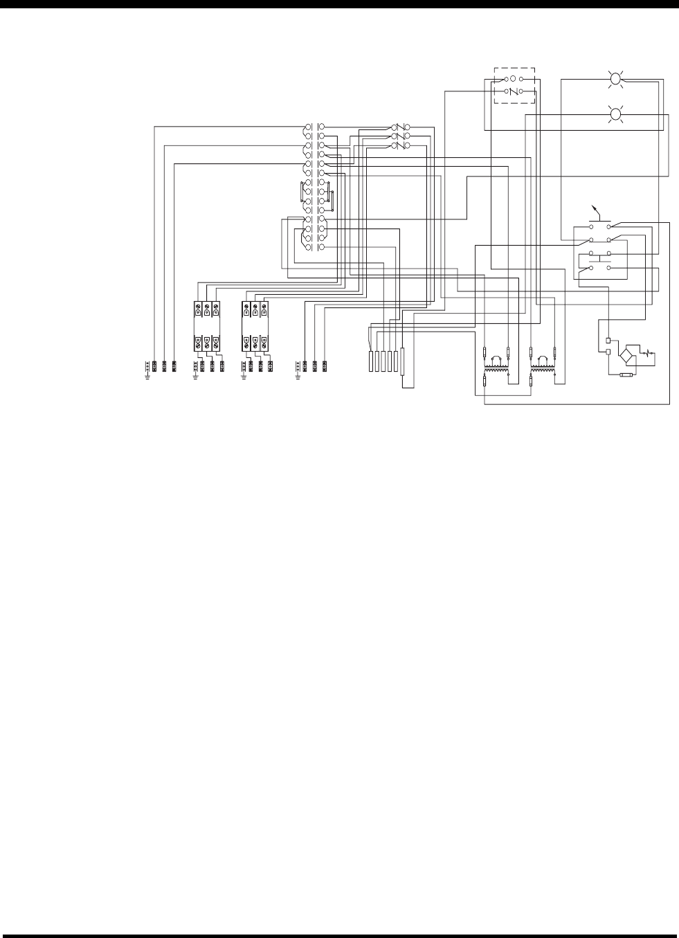
Figure 3 - SBP Electrical Schematic 450V
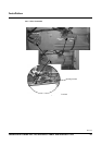
UPS Maintenance
Bypass Switch
UPS Bypass
1
3
5
7
9
11
13
15
17
19
1
3
5
7
2
4
6
8
10
12
14
16
18
20
2
4
6
8
BYP
UPS
BYP
BYP
BYP
BYP
UPS
UPS
UPS
UPS
UPS
BYP
BYP
BYP
1
3
5
2
4
6
UPS Input
Disconnect
Switch
On-Off
Relay
R
14
13
1
9
"UPS in Static Bypass" Ind. Light
"UPS in Maintenance Bypass" Ind. Light
R
G
Keyed Solenoid Lock Release Switch
Lock
Release
0X
0X
X0
X0
13
22
31
43
14
21
32
44
Solenoid Lock
Mechanism
(Energize to Unlock)
N
120 VAC
X
+
-
120 VDC
5A
440, 450, 480
VAC Primary
440, 450, 480
VAC Primary
120 VAC
Secondary
XFMR 1
120 VAC
Secondary
XFMR 2
H1 H3
H2
H4
H1
H3 H2
H4
X1
X1
X2
X2
F1A
1A
12345
6
CNN
DC
Auxiliary Switch Circuit
GL1L2L3
AC Input to UPS
F4-F5-F6
F1-F2-F3
GL1L2L3
AC Line Input
G L1 L2 L3 G L1 L2 L3
AC Output from UPS
AC Output
to Critical Load
Notes:
1. F1, F2, F3 = 15A
2. F4, F5, F6 = 25A
3. All AC power cabling is 3 wire + Ground at 450VAC 3-phase.
4. Installation must comply with all applicable national and local codes.