


3Automatic Transfer Switch—Installation and Quick Start
Overview
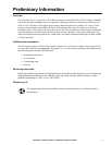
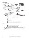
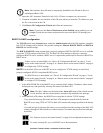
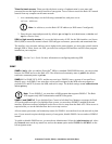
Front panel
Item Description
Source A and B LEDs Provide information about the input voltage from each source.
If the RMS input voltage and the measured frequency are
within the selected tolerance range, the corresponding indicator
will light.
In a normal operating condition (full source redundancy), both
LEDs are illuminated.
Connector LEDs Indicate which source is being used for the output (only one
arrow will be lit at any time). The combination of Source
LEDs, Connector LEDs, and Output LED provide a graphical
view of the power flow through the ATS.
Output LED Shows that voltage is available at the output for the ATS.
Preference key Sets the preferred source to supply power to the load
equipment. In normal operation, if both sources are available,
the ATS will use the preferred source. Press the Preference key
to change the preferred source. Press and hold for ten seconds
to restart the ATS. The restart occurs without resetting
communications and is confirmed when both status LEDs flash
off, then on.
Preference A and B
LEDs
Indicate which of the two sources is selected as the preferred
source. If both LEDs are off, neither source is selected. If the
sources are asynchronous, the LED for the selected source will
flash once per second.
Reset switch Restarts ATS network and serial communication.
Digital display Digital display of the current used by the ATS and attached
devices:
• Shows the aggregate current for the bank/phase
corresponding to the Bank/Phase Indicator
LED that is
illuminated.
• Cycles through the banks/phases in 3-second intervals.
Control key • Press to change the bank/phase of the current displayed on the
digital display.
• Press and hold for five seconds to display the IP address of the
AT S .
Link - Rx/Tx
10
/
100
Status
Serial Port
Reset
Press to
select data
Amps
- Warning
- OK
- Overload
A
B
Output
Input
Preference
AB
A
utomatic
Transfer Switch
B1 B2
- Warning
- OK
- Overload
TOTAL
pdu0392a