SURTA 1500XL/1500XLJ/2200XL Series 100/120 Vac Tower/Rack-Mount 2U4
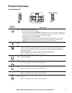
Front Display Panel
Feature Description
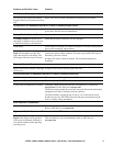
The UPS has a diagnostic feature that indicates utility voltage.
The UPS starts a self-test as part of this procedure. The self-test does not affect voltage
display.
Press and hold the
ON button to view utility voltage bar graph indicator. As soon as the On
Line LED starts flashing indicating a self-test is in progress, the five-LED Battery Charge
indicator to the right of the display panel will show utility input voltage.
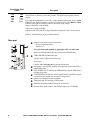
Refer to diagram for voltage reading.
Values are not listed on the UPS.
Indicators on the UPS show the voltage is between the displayed value on list and the next
higher value.
Refer to “Troubleshooting” on page 10 in this manual.
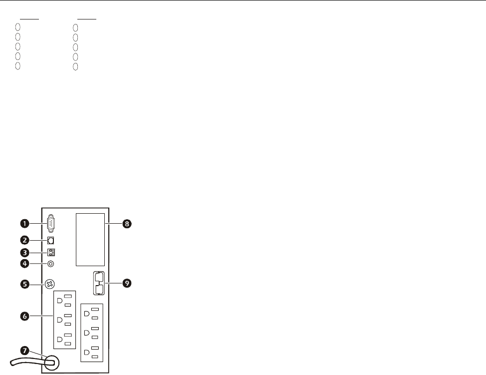
Rear panel
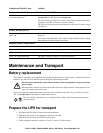
SERIAL COM-serial communication port for:
Power management software
Interface kits
Use only interface kits supplied or approved by APC. Any other serial
interface cable will be incompatible with UPS connector.
Serial and USB communication ports cannot be used simultaneously.
USB COM-USB communication port
120 Vac models: USB communication cable
100 Vac models: USB communication cables and software are available as
accessories.
Contact APC at www.apc.com for purchase information.
Emergency Power Off (EPO) terminal allows the user to connect the UPS to a
central EPO system.
SITE WIRING FAULT indicator-the LED illuminates when the UPS detects a
building wiring fault.
TVSS GND-The UPS features a chassis ground located on the UPS rear panel
for connecting the ground leads on transient voltage devices
Outlets for connecting electronic equipment.
UPS power cable for connecting to utility power.
SmartSlot for optional NMC or PowerChute accessories.
External battery pack connector. The UPS will support up to 10 XLBPs.
118.0
100V
108.7
99.3
90.0
80.6
138.2
120V
128.8
119.5
110.1
100.8
suo0523a


