


11 Operation Manual Universal Transfer Switch UTS6 UTS6H UTS6BI UTS10BI
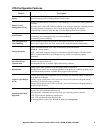
Circuit setup options
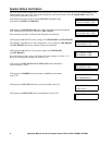
Setup Option 1-Circuit Load Type
A UTS can be configured for many load types. These and other load types may be labeled on the building circuit breaker
panel.
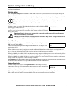
Setup Option 2-Source
The factory default setting for the backup power source is GEN (generator). Use the down/up arrow keys to establish the
backup power source for a selected circuit.
GEN-backup power source will be a connected generator.
UNINTERRUPTIBLE-there is continuous backup power supplied by a UPS. Utility power flows into the UPS and from
the UPS to the connected load. This provides power and protection for the load during any utility power fluctuation.
NONE-there will be no backup power source available.
EITHER-backup power source will be either a connected generator or a UPS.
UPS-backup power source will be a connected UPS.
Note: Backup power source availability varies for some circuits.
The UPS and EITHER backup power source options are not available for:
• circuit1 on all units
• the designated 240 V circuits on the UTS6BI or the UTS10BI
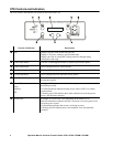
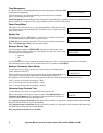
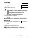
Delayable Circuits
The factory default setting is NO. Setting a circuit to YES, enables the UTS to run
ALM for the individual circuit selected.
The UTS provides intelligent load management, defined by APC as adaptive load
management (ALM).
The Delayable Circuits setup option works in conjunction with Load Shedding and Time Management. The Delayable
Circuits setup option requires that both Load Shedding and Time Management under System Setup, be set to ON. Once
Load Shedding and Time Management have been enabled each circuit can be individually set to YES enabling the
Delayable Circuits feature.
• Load Shedding is used with time management to ensure loads receive adequate power over extended periods
of time. When a backup power source is nearing an overload condition, ALM intelligence sheds (drops),
select loads and then reconnects the loads when adequate power becomes available. ALM selects the most
suitable loads to drop and reconnect at any given time minimizing overall load disruption, and maximizing
backup power capability.
• When load shedding is disabled (ALM is off), overload conditions can occur causing a generator to stall, a
circuit breaker to trip, or loads may experience severe low voltage conditions.
• Time Management is used with load shedding to ensure loads receive adequate power over extended periods
of time. There are two time management settings, Maximum Off and Minimum On. These can be set for
each circuit through Circuit Setup. When this feature is on, time management ensures that loads are not shed
(power is not removed), for more than the set Maximum Off time. This feature also ensures that loads
receive power for the Minimum On time set in circuit setup.
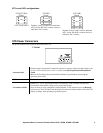
LIGHTS
GARAGE DOOR OPENER
FURNACE (HOT AIR)
FURNACE (HOT WATER)
FREEZER
AIR CONDITIONER
NONE
OTHER
SUMP PUMP
SPRINKLER SYSTEM
SECURITY SYSTEM
REFRIGERATOR
WELL PUMP (or other motor driven
device i.e. blower or exhaust fan)
MICROWAVE OVEN
CKT1 DELAYABLE
NO