


5 Operation Manual Universal Transfer Switch UTS6 UTS6H UTS6BI UTS10BI
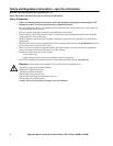
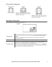
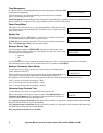
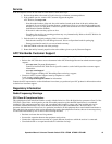
UTS circuit LED configurations
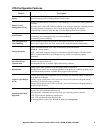
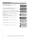
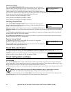
UTS Power Connectors
The power connectors are located on the front of the UTS.
120 V circuits ONLY
Together, circuits 5 and 6 form a dedicated
240 V circuit. DO NOT use these circuits as
individual 120 V circuits.
Together, circuits 9 and 10 form a dedicated
240 V circuit. DO NOT use these circuits as
individual 120 V circuits.
UTS10BI
Generator Inlet
• Generator inlet is hardwired. Connection must be in a remote, outdoor location. Refer to the
Connect UTS to Backup Power Sources section in the Site Preparation and Installation
Guide.
• Refer to the Site Preparation and Installation Guide for specifications concerning the
generator power cable.
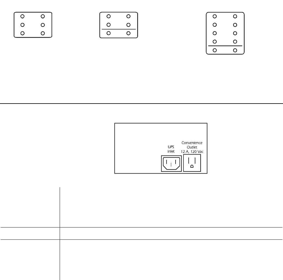
UPS Inlet IEC 320 connector for UPS power cable.
Convenience Outlet
• NEMA 5-15, 120 V convenience outlet for connecting a UPS or another selected load.
• Convenience outlet utilizes utility power or generator power.
• If any circuits are to be configured as uninterruptible, a UPS must be used as the Backup2
power source. The UPS input cord should plug into the convenience outlet to allow the UPS
battery to charge while operating on generator power.
UTS6/UTS6H
120 V
1
3
5
2
4
6
Circuit
120 V
240 V
1
3
5
2
4
6
Circuit
UTS6BI
UTS10BI
120 V
240 V
1
3
5
7
9
2
4
6
8
10
Circuit
bu164a