


Operation Manual Universal Transfer Switch UTS6 UTS6H UTS6BI UTS10BI4
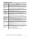
UTS Controls and Indicators
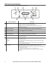
The UTS controls and indicators are located on the front of the UTS.
Control or Indicator Description
LCD • Displays two lines with 20 characters per line
• Displays UTS status, warnings, general information
• Displays the value or setting that is being entered or changed during
configuration and setup
System Status button Cycles the UTS through the default or selected system status options
System Setup button Used to configure the UTS system options
Circuit Status button Cycles the UTS through the circuits displaying the status of each on the LCD
Circuit Setup button Used to configure the UTS individual circuit options
Down/Up arrow buttons Used to scroll through steps for configuration and to scroll between status and
informational displays
Source LEDs
Utility
Generator
UPS
• Solid green LED illumination indicates that the power source is ON and is
functioning normally
• No LED illumination indicates that the power source is OFF or is outside
specified limits
• A flashing green LED indicates that a fault condition exists for that power
source, and should be corrected
Circuit LEDs The number of circuit LEDs varies dependent on the model of UTS
• Red LED illumination indicates that the UTS circuit is receiving power from
one of the power sources
• No illumination indicates that circuit is receiving no power
• A flashing red LED indicates that a fault condition exists and should be
corrected
bu163a