


Aruba AP 60/61 3
Installation Guide
Introduction
Chapter 1
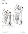
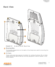
Aruba AP60–Two Reverse Polarity SMA (RP-SMA) connectors for attaching
separate antennas (not included). For details, see “Aruba 60 Detachable
Antennas” on page 22. (The AP60 requires that both connectors be used in
ArubaOS 2.2 releases or lower. Single antenna operation is supported with
ArubaOS 2.3 or higher.)
NOTE: When facing the A60 as shown in Figure 1-1, the antenna connector
on the left is for antenna 1, and the connector on the right is for
antenna 2 in a diversity configuration.
Aruba AP61–Built-in swivel array with dual, tri-band, omnidirectional
antennas
Indicator LEDs
During operation, the Aruba AP 60/61 LEDs provide the following information:
N
OTE: LEDs on the Mobility Controller provide additional status and security
information about connected APs.See the ArubaOS User Guide for more
information.
Air Vents
These vents promote proper air circulation for cooling the device. Do not allow
these vents to be obstructed by mounting equipment, network cables, or any
other material.
TABLE 1-1 Aruba AP 60/61 LEDs
LED State Description
PWR Off The device is off - no power.
Green-Solid The device is powered and operating.
ENET Off No link on the FE port. No connection to the
network.
Green-Solid Ethernet link detected on the FE port.
Green-Flashing Transmitting or receiving data across the FE
port. Flashing rate is proportional to network
activity.
WLAN Off The wireless interface is disabled or down.
Green-Solid The wireless interface is enabled and
functioning as an Access Point.
Green-Flashing The wireless interface is enabled and
functioning as an Air Monitor.
A
B
2
A
B
C
3