


7
Chapter 2. Hardware Installation
This chapter describes the front and rear panels of the FM2017, and explains how to install, mount and
apply power to the switch.
Package Contents
The switch is shipped with the following items:
• Switch
• AC power cord
• Four (4) Rubber feet
• Rack mount Kit
• RS-232 cable
• User’s Manual (this document)
Compare the contents of your switch’s package against the items listed above. If any of the items is missing
or damaged, contact your dealer immediately for service.
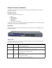
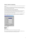
Front Panel
The front panel of the FM2017 contains the LED Indicators, the console port, the 16 10/100Mbps ports and
the 100FX module slot.
LED Indicators
The LED Indicators give real-time information of systematic operation status. The following table provides
descriptions of LED status and their meaning.
LED Status Description
Power Green
Off
Power is on.
Power is not connected, or is turned off.
100M Green
Off
A valid 100Mbps link has been established on the port.
A 10Mbps link has been established on the port, or no device is detected.
Link/Activity Green
Blinking
Off
A valid connection to another device has been established on the port.
Traffic is detected on the port (transmitting or receiving).
No device is attached.
Full-Duplex Yellow
Blinking
Off
The port is operating in full-duplex.
The port is operating in half-duplex.
No device is attached, or the port is in half-duplex mode.