Operating Manual - FR-8 and FR-16 Remote Level Controller
2
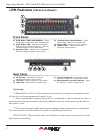
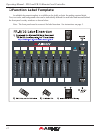
Front Panel
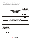
1) Push Button LED Label Window - Insert
switch label made from Ashly template doc
2) Push Button LED - Used to switch fader
Mute or fader A/B Source Select. LED also
indicates signal level or fader status
3) Channel Fader - Adjusts level of targeted
DSP gain stage or output mixer source
4) Channel Fader Label Window - Insert
switch label made from template doc
5) Power LED - Shows device is powered
6) Master Fader - Adjusts level of all
assigned channel faders
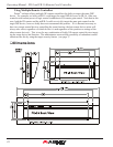
Rear Panel
1) RJ-45 Jack - Connects to Ethernet
Network with PoE or PoE injector
2) Link LED - Shows network is connected
3) Data LED - Shows Data is transferring
4) Lockout Connector - Used with contact
closure to disable all front panel controls
5) Serial Number and MAC Address - Used
for warranty or ash programming
FR Features (FR-8 not shown)
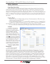
On Startup:
1. When the FR-8 or FR-16 is rst connected or powered on, it attempts to communicate with
all devices it has been programmed to control, if any.
2. Once communication with the targeted device is established, it waits to transmit any fader or
switch position data until a control is physically changed by the user. At that point only the data for
that control is sent.
***This feature prevents sudden and unexpected changes when reconnecting or re-starting the
FR remote control, as well as when a new preset is recalled to the host device.
PLEASE NOTE: When in doubt, make sure all faders are either in the correct position or fully
down before reconnecting


