


62 Chapter 5
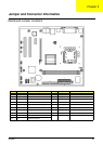
Jumper Settings
This section explains how to set jumpers for correct configuration of the mainboard.
Setting Jumpers
Use the motherboard jumpers to set system configuration options. Jumpers with more than one pin are
numbered. When setting the jumpers, ensure that the jumper caps are placed on the correct pins.
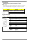
System Board Jumper Setting
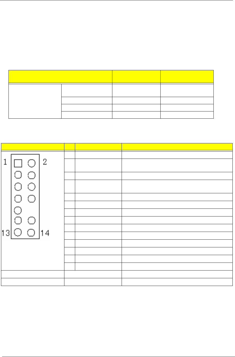
System Board Header Setting
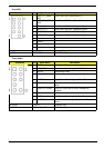
Front Panel
Features Default setting
Remark (color and
other)
On-board Jumper and
default setting (See Pin
definition for the detail)
CLR_CMOS(PIN2_3)1
& default setting
2-3 : Normal (Default) 1-2 : Clear CMOS
2-3 : Normal (Default)
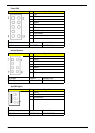
Illustration Pin Signal Name Description
1 5V_SYS Hard disk LED pull-up(330 ohm) to 5V_SYS
2 GPIO_GRN_HDR_R Pull-up(330 ohm) to 5V_SB_SYS and connect to
SIO GPIO
3 HDD_LED_R Hard disk active LED
4 GPIO_YLW_HDR_R Pull-up(330 ohm) to 5V_SB_SYS and connect to
SIO GPIO
5 GND Reset button
6 PSIN Power Button
7 ICH_SYS_RSTJ ICH_SYS_RSTJ
8 GND Ground
9 5V_SYS 5V_SYS
10 KEY Key
11 NC Reserved. Do not use
12 5V_SB LAN LED pull-up(330 ohm) to 5V_SB
13 NC Reserved. Do not use
14 LAN_ACTJ Lan active LED
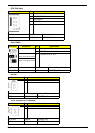
Silk Screen Footprint Schematic Part
FP1 h2x7mzo10h85 HEADER_2X7_10