


ASUS CUWE User’s Manual 39
3. HARDWARE SETUP
Connectors
3. H/W SETUP
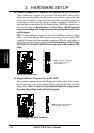
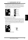
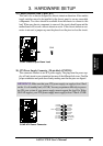
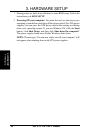
20) SMBus Connector (5-1 pin SMB)
This connector allows you to connect SMBus (System Management Bus) de-
vices. SMBus devices communicate by means of the SMBus with an SMBus
host and/or other SMBus devices. SMBus is a specific implementation of an I
2
C
bus, which is a multi-device bus; that is, multiple chips can be connected to the
same bus and each one can act as a master by initiating data transfer.
SMBCLK
Ground
SMBDATA
+5V
1
CUWE SMBus Connector
SMB
010101
®
CUWE
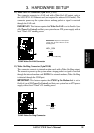
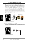
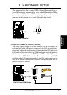
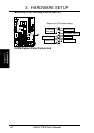
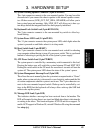
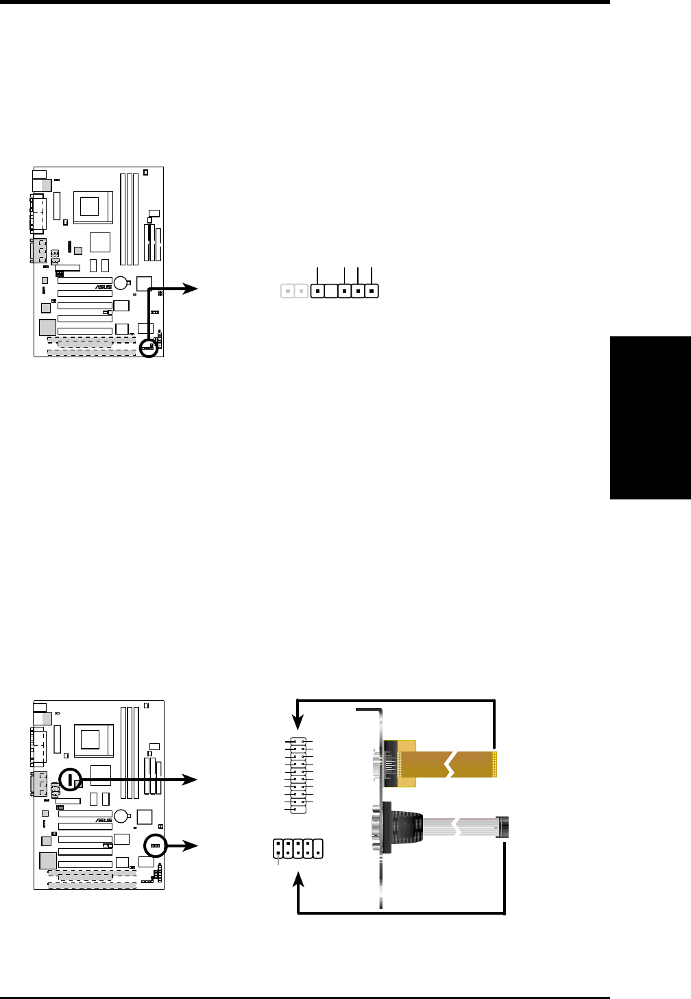
21) Digital LCD Header (20-1 pin DFP) (optional)
This header requires a digital LCD cable connector. For the LCD model, the
individual serial cable with bracket is replaced with the LCD and serial combi-
nation cable with bracket (as shown here). Connect the digital LCD cable to the
LCD header and the serial cable to the COM2 header and mount the bracket to
the chassis on a free expansion slot. NOTE: If both CRT and digital LCD moni-
tors are used, the CRT will take precedent. This connector is for a digital LCD
panel; an analog LCD panel comes with a 15-pin VGA cable connector to be
used on the monitor connector. The connectors with bracket shown here are
provided with the LCD model.
010101
®
CUWE
CUWE LCD and COM2 Bracket
DFP
to DFP Header
to COM2 Header
Pin 1
COM2
1
5VLTVCL
HPG
GND
TXC+
TX0-
TX1+
TX2-
GND
(NC)
5VLTVDA
0+5V
TXC-
GND
TX0+
TX1-
GND
TX2+
11
10 20
GND
(NC)